// Ardumower Sunray
// Copyright (c) 2013-2020 by Alexander Grau, Grau GmbH
// Licensed GPLv3 for open source use
// or Grau GmbH Commercial License for commercial use (
http://grauonline.de/cms2/?page_id=153)
/* see Wiki for installation details:
http://wiki.ardumower.de/index.php?title=Ardumower_Sunray
requirements:
+ Ardumower chassis and Ardumower motors
+ Ardumower PCB 1.3
+ Adafruit Grand Central
M4 (highly recommended) or
Arduino Due
+ Ardumower BLE UART module (HM-10/CC2540/CC2541)
+ optional: Ardumower IMU (MPU6050/MPU9150/MPU9250/MPU9255) - choose your IMU below
+ optional: Ardumower WIFI (ESP8266 ESP-01 with stock firmware)
+ optional: HTU21D temperature/humidity sensor
+ optional: sonar, bumperduino, freewheel sensor
+ Ardumower
RTK (ublox F9P)
1. Rename file 'config_example.h' into 'config.h'
2. Configure the options below and finally compile and upload this project.
Adafruit Grand Central
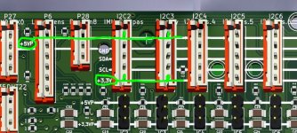
M4 NOTE: You have to add SDA, SCL pull-up resistors to the board
and deactivate Due clone reset cicuit (JP13):

wiki.ardumower.de
Arduino Due UPLOAD NOTE:
If using
Arduino Due 'native' USB port for uploading, choose board '
Arduino Due native' in the
Arduino IDE and COM port '
Arduino Due native port'.
If using
Arduino Due 'programming' USB port for uploading, choose board '
Arduino Due programming' in the
Arduino IDE and COM port '
Arduino Due programming port'.
Also, you may choose the serial port below for serial monitor output (CONSOLE).
*/
#ifdef __cplusplus
#include "udpserial.h"
#include "sdserial.h"
#include "src/agcm4/adafruit_grand_central.h"
#ifdef __linux__
#include "src/raspi/raspi.h"
#include <Console.h>
#endif
#endif
//#define DRV_SERIAL_ROBOT 1
#define DRV_ARDUMOWER 1 // keep this for Ardumower
// ------- Bluetooth4.0/BLE module -----------------------------------
// see Wiki on how to install the BLE module and configure the jumpers:
//
https://wiki.ardumower.de/index.php?title=Ardumower_Sunray#Bluetooth_BLE_UART_module
#define ENABLE_PASS 1 // comment out to disable password authentication
#define PASS 123456 // choose password for WiFi/BLE communication
// -------
RTK GPS module -----------------------------------
// see Wiki on how to install the GPS module and configure the jumpers:
//
https://wiki.ardumower.de/index.php?title=Ardumower_Sunray#Bluetooth_BLE_UART_module
// -------- IMU sensor ----------------------------------------------
// choose one MPU IMU (make sure to connect AD0 on the MPU board to 3.3v)
// verify in CONSOLE that your IMU was found (you will hear 8 buzzer beeps for automatic calibration at start)
// see Wiki for wiring, how to position the module, and to configure the I2C pullup jumpers:
//
https://wiki.ardumower.de/index.php?title=Ardumower_Sunray#IMU.2C_sensor_fusion
//#define MPU6050
//#define MPU9150
#define MPU9250 // also choose this for MPU9255
// should the mower turn off if IMU is tilt over? (yes: uncomment line, no: comment line)
#define ENABLE_TILT_DETECTION 1
// ------- SD card map load/resume and logging ---------------------------------
// all serial console output can be logged to a (FAT32 formatted) SD card
// NOTE: for full log file inspections, we will need your sunray.ino.elf binary
// (you can find out the location of the compiled .elf file while compiling with verbose compilation switched on
// via 'File->Preferences->Full output during compile') - detailed steps here:
//
https://wiki.ardumower.de/index.php?title=Ardumower_Sunray#SD_card_module
//
https://wiki.ardumower.de/index.php?title=Ardumower_Sunray#SD_card_logging
//#define ENABLE_SD 1 // enable SD card services (resuming, logging)? (uncomment to activate)
//#define ENABLE_SD_LOG 1 // enable SD card logging? (uncomment to activate)
//#define ENABLE_SD_RESUME 1 // enable SD card map load/resume on reset? (uncomment to activate)
// ------ odometry -----------------------------------
// values below are for Ardumower chassis and Ardumower motors
// see Wiki on how to configure the odometry divider:
//
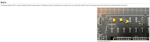
https://wiki.ardumower.de/index.php?title=Ardumower_Sunray#PCB1.3_odometry_divider
// NOTE: It is important to verify your odometry is working accurate.
// Follow the steps described in the Wiki to verify your odometry returns approx. 1 meter distance for
// driving the same distance on the ground (without connected GPS):
//
https://wiki.ardumower.de/index.php?title=Ardumower_Sunray#Odometry_test
//
https://forum.ardumower.de/threads/andere-räder-wie-config-h-ändern.23865/post-41732
#define WHEEL_BASE_CM 36 // wheel-to-wheel distance (cm)
#define WHEEL_DIAMETER 250 // wheel diameter (mm)
//#define ENABLE_ODOMETRY_ERROR_DETECTION true // use this to detect odometry erros
#define ENABLE_ODOMETRY_ERROR_DETECTION false
// choose ticks per wheel revolution :
// ...for the 36mm diameter
motor (blue cap)
https://www.marotronics.de/2-x-36er-DC-Planeten-Getriebemotor-24-Volt-mit-HallIC-30-33-RPM-8mm-Welle
//#define TICKS_PER_REVOLUTION 1310 / 2 // odometry ticks per wheel revolution
// ...for the 36mm diameter
motor (black cap)
https://www.marotronics.de/MA36-DC-...-30-33-RPM-8mm-Welle-ab-2-Stueck-Staffelpreis
// #define TICKS_PER_REVOLUTION 975 / 2
// ...for the newer 42mm diameter
motor (green connector)
https://www.marotronics.de/MA42-DC-...-30-33-RPM-8mm-Welle-ab-2-Stueck-Staffelpreis
// #define TICKS_PER_REVOLUTION 696 / 2 // odometry ticks per wheel revolution
// ...for the older 42mm diameter
motor (white connector)
https://wiki.ardumower.de/images/d/d6/Ardumower_chassis_inside_ready.jpg
#define TICKS_PER_REVOLUTION 1050 / 2 // odometry ticks per wheel revolution
// ...for the
brushless motor april 2021
https://wiki.ardumower.de/index.php?title=Datei:BLUnit.JPG
//#define TICKS_PER_REVOLUTION 1300 / 2 // 1194/2 odometry ticks per wheel revolution
// #define TICKS_PER_REVOLUTION 304 // odometry ticks per wheel revolution (RM18)
// ----- gear motors --------------------------------------------------
#define MOTOR_DRIVER_BRUSHLESS 1 // uncomment this for new
brushless motor drivers
#define MOTOR_OVERLOAD_CURRENT 0.8 // gear motors overload current (amps)
//#define USE_LINEAR_SPEED_RAMP true // use a speed ramp for the linear speed
#define USE_LINEAR_SPEED_RAMP false // do not use a speed ramp
//
motor speed control (PID coefficients) - these values are tuned for Ardumower motors
// general information about PID controllers:
https://wiki.ardumower.de/index.php?title=PID_control
#define MOTOR_PID_KP 2.0 // do not change 2.0 (for non-Ardumower motors or if the
motor speed control is too fast you may try: KP=1.0, KI=0, KD=0)
#define MOTOR_PID_KI 0.03 // do not change 0.03
#define MOTOR_PID_KD 0.03 // do not change 0.03
// ----- mowing
motor -------------------------------------------------
#define MOW_OVERLOAD_CURRENT 2.0 // mowing
motor overload current (amps)
// should the direction of mowing
motor toggle each start? (yes: true, no: false)
#define MOW_TOGGLE_DIR true
//#define MOW_TOGGLE_DIR false
// should the
motor overload detection be enabled?
//#define ENABLE_OVERLOAD_DETECTION true
#define ENABLE_OVERLOAD_DETECTION false
// should the
motor fault (error) detection be enabled?
#define ENABLE_FAULT_DETECTION true
//#define ENABLE_FAULT_DETECTION false // use this if you keep getting '
motor error'
// ------ WIFI module (ESP8266 ESP-01 with ESP firmware 2.2.1) --------------------------------
// NOTE: all settings (maps, absolute position source etc.) are stored in your phone - when using another
// device for the WIFI connection (PC etc.), you will have to transfer those settings (share maps via app,
// re-enter absolute position source etc) !
// see Wiki on how to install the WIFI module and configure the WIFI jumpers:
//
https://wiki.ardumower.de/index.php?title=Ardumower_Sunray#Bluetooth_BLE_UART_module
#define START_AP false // should WIFI module start its own access point?
#define WIFI_IP 192,168,2,15 // choose IP e.g. 192,168,4,1 (comment out for dynamic IP/DHCP) - NOTE: use commans instead of points
#define WIFI_SSID "myssid" // choose WiFi network ID
#define WIFI_PASS "mypassword" // choose WiFi network password
// client (app) ---> server (robot)
#define ENABLE_SERVER true // must be enabled if robot should act as server (recommended)
//#define ENABLE_SERVER false // must be disabled if robot should act as client (requires external relay server)
// a relay server allows to access the robot via the Internet by transferring data from app to robot and vice versa (not available yet, highly experimental)
// client (app) ---> relay server <--- client (robot)
#define ENABLE_RELAY false // must be enabled to use relay server
#define RELAY_USER "username" // choose a unique user name/number!
#define RELAY_MACHINE "robot1" // choose a unique robot id
#define RELAY_HOST "grauonline.net" // relay server name
#define RELAY_PORT 5000 // relay server port
//#define ENABLE_UDP 1 // enable console for UDP? (for developers only)
#define UDP_SERVER_IP 192,168,2,56 // remote UDP IP and port to connect to
#define UDP_SERVER_PORT 4210
// --------- NTRIP client (linux only, highly experimental) ---------------------------------
#define NTRIP_HOST "195.227.70.119" // sapos nrw
#define NTRIP_PORT 2101
#define NTRIP_MOUNT "VRS_3_4G_NW"
#define NTRIP_USER "user"
#define NTRIP_PASS "pass"
// ------ MQTT (highly experimental - ENABLE_SERVER must be set to false for this to work :-/ ) -----------------------------
// you can access your robot using a MQTT broker - choose a topic prefix for your robot below - available MQTT topics:
// robot1/cmd (cmd can be: start, stop, dock)
// robot1/op (current robot operation as text)
// robot1/gps/sol (current gps solution as text)
// robot1/gps/pos (current gps position as text)
//#define ENABLE_MQTT true // start MQTT client? (true for yes, false for no)
#define ENABLE_MQTT false
#define MQTT_TOPIC_PREFIX "robot1" // the MQTT topic prefix for your robot
#define MQTT_SERVER "192.168.2.47" // your MQTT broker IP or hostname (e.g. "broker.mqtt-dashboard.com")
#define MQTT_PORT 1883
// ------ ultrasonic sensor -----------------------------
// see Wiki on how to install the ultrasonic sensors:
//
https://wiki.ardumower.de/index.php?title=Ardumower_Sunray#Ultrasonic_sensor
//#define SONAR_ENABLE true
#define SONAR_ENABLE false
#define SONAR_TRIGGER_OBSTACLES true // should sonar be used to trigger obstacles? if not, mower will only slow down
#define SONAR_LEFT_OBSTACLE_CM 10 // stop mowing operation below this distance (cm)
#define SONAR_CENTER_OBSTACLE_CM 10 // stop mowing operation below this distance (cm)
#define SONAR_RIGHT_OBSTACLE_CM 10 // stop mowing operation below this distance (cm)
// ------ rain sensor ----------------------------------------------------------
//#define RAIN_ENABLE true // if activated, mower will dock when rain sensor triggers
#define RAIN_ENABLE false
// ------ time-of-flight distance sensor (VL53L0X) -----------------------------
// do not use this sensor (not recommended)
//#define TOF_ENABLE true
#define TOF_ENABLE false
#define TOF_OBSTACLE_CM 100 // stop mowing operation below this distance (cm)
// ------ bumper sensor (bumperduino, freewheel etc.) ----------------
// see Wiki on how to install bumperduino or freewheel sensor:
//
https://wiki.ardumower.de/index.php?title=Bumper_sensor
//
https://wiki.ardumower.de/index.php?title=Free_wheel_sensor
// #define BUMPER_ENABLE true
#define BUMPER_ENABLE false
#define BUMPER_DEADTIME 1000 // linear motion dead-time (ms) after bumper is allowed to trigger
// ----- battery charging current measurement (INA169) --------------
// the Marotronics charger outputs max 1.5A
// (
https://www.marotronics.de/Ladegera...kus-24V-mit-Status-LED-auch-fuer-Li-Ion-Akkus )
// so we are using the INA169 in non-bridged mode (max. 2.5A)
// (
https://www.marotronics.de/INA169-Analog-DC-Current-Sensor-Breakout-60V-25A-5A-Marotronics )
//#define CURRENT_FACTOR 0.5 // PCB1.3 (non-bridged INA169, max. 2.5A)
//#define CURRENT_FACTOR 1.0 // PCB1.3 (bridged INA169, max. 5A)
#define CURRENT_FACTOR 1.98 //
PCB1.4 (non-bridged INA169, max. 2.5A)
//#define CURRENT_FACTOR 2.941 //
PCB1.4 (bridged INA169, max. 5A)
#define GO_HOME_VOLTAGE 21.5 // start going to dock below this voltage
// The battery will charge if both battery voltage is below that value and charging current is above that value.
#define BAT_FULL_VOLTAGE 28.7 // start mowing again at this voltage
#define BAT_FULL_CURRENT 0.2 // start mowing again below this charging current (amps)
//
https://wiki.ardumower.de/index.php?title=Ardumower_Sunray#Automatic_battery_switch_off
#define BAT_SWITCH_OFF_IDLE false // switch off if idle (JP8 must be set to autom.)
#define BAT_SWITCH_OFF_UNDERVOLTAGE true // switch off if undervoltage (JP8 must be set to autom.)
// ------ GPS ------------------------------------------
// NOTE: if you experience GPS checksum errors, try to increase UART FIFO size:
// 1.
Arduino IDE->File->Preferences->Click on 'preferences.txt' at the bottom
// 2. Locate file 'packages/
arduino/hardware/sam/xxxxx/cores/
arduino/RingBuffer.h'
// (for Adafruit Grand Central
M4: 'packages\adafruit\hardware\samd\xxxxx\cores\
arduino\RingBuffer.h')
// change: #define SERIAL_BUFFER_SIZE 128 into into: #define SERIAL_BUFFER_SIZE 1024
//#define REQUIRE_VALID_GPS true // mower will pause if no float and no fix GPS solution during mowing
#define REQUIRE_VALID_GPS false // mower will continue to mow if no float or no fix solution
#define GPS_SPEED_DETECTION true // will detect obstacles via GPS feedback (no speed)
//#define GPS_SPEED_DETECTION false
// detect if robot is actually moving (obstacle detection via GPS feedback)
#define GPS_MOTION_DETECTION true // if robot is not moving trigger obstacle avoidance
//#define GPS_MOTION_DETECTION false // ignore if robot is not moving
#define GPS_MOTION_DETECTION_TIMEOUT 10 // timeout for motion (secs)
// configure ublox f9p with optimal settings (will be stored in f9p RAM only)
// NOTE: due to a PCB1.3 bug GPS_RX pin is not working and you have to fix this by a wire:
//
https://wiki.ardumower.de/index.php?title=Ardumower_Sunray#PCB1.3_GPS_pin_fix (see step 2)
#define GPS_CONFIG true // configure GPS receiver (recommended - requires GPS wire fix above!)
//#define GPS_CONFIG false // do not configure GPS receiver (no GPS wire fix required)
#define GPS_CONFIG_FILTER true // use signal strength filter? (recommended to get rid of 'FIX jumps')
//#define GPS_CONFIG_FILTER false // use this if you have difficulties to get a FIX solution
// ------ experimental options -------------------------
#define OSTACLE_AVOIDANCE true // try to find a way around obstacle
//#define OSTACLE_AVOIDANCE false // stop robot on obstacle
#define OBSTACLE_DIAMETER 1.2 // choose diameter of obstacles placed in front of robot (m) for obstacle avoidance
// detect robot being kidnapped? robot will go into error if distance to tracked path is greater than 1m
//#define KIDNAP_DETECT true
#define KIDNAP_DETECT false
// drive curves smoothly?
#define SMOOTH_CURVES true
//#define SMOOTH_CURVES false
//#define ENABLE_PATH_FINDER true // path finder is experimental (can be slow - you may have to wait until robot actually starts)
#define ENABLE_PATH_FINDER false
#define ALLOW_ROUTE_OUTSIDE_PERI_METER 1.0 // max. distance (m) to allow routing from outside perimeter
// (increase if you get 'no map route' errors near perimeter)
// is a docking station available?
//#define DOCKING_STATION true // use this if docking station available and mower should dock automatically
#define DOCKING_STATION false // mower will just stop after mowing instead of docking automatically
//#define DOCK_AUTO_START true // robot will automatically continue mowing after docked automatically
#define DOCK_AUTO_START false // robot will not automatically continue mowing after docked automatically
// stanley control for path tracking - determines gain how fast to correct for lateral path errors
#define STANLEY_CONTROL_K_NORMAL 0.5 // 0.5 for path tracking control when in normal or fast motion
#define STANLEY_CONTROL_K_SLOW 0.1 // 0.1 for path tracking control when in slow motion (e.g. docking tracking)
// activate support for model R/C control?
// use PCB pin 'mow' for R/C model control speed and PCB pin 'steering' for R/C model control steering,
// also connect 5v and GND and activate model R/C control via PCB P20 start button for 3 sec.
// more details:
https://wiki.ardumower.de/index.php?title=Ardumower_Sunray#R.2FC_model
//#define RCMODEL_ENABLE true
#define RCMODEL_ENABLE false
// button control (turns on additional features via the POWER-ON button)
#define BUTTON_CONTROL true // additional features activated (press-and-hold button for specific beep count:
// 1 beep=start/stop, 5 beeps=dock, 3 beeps=R/C mode ON/OFF)
//#define BUTTON_CONTROL false // additional features deactivated
// --------- serial monitor output (CONSOLE) ------------------------
// which
Arduino Due USB port do you want to your for serial monitor output (CONSOLE)?
//
Arduino Due native USB port => choose SerialUSB
//
Arduino Due programming port => choose Serial
#ifdef _SAM3XA_
#define BOARD "
Arduino Due"
#define CONSOLE SerialUSB //
Arduino Due: do not change (used for Due native USB serial console)
#elif __SAMD51__
#define BOARD "Adafruit Grand Central
M4"
#define CONSOLE Serial // Adafruit Grand Central
M4
#elif __linux__
#define BOARD "Raspberry PI"
#define CONSOLE Console
#endif
// ------- serial ports and baudrates---------------------------------
#define CONSOLE_BAUDRATE 115200 // baudrate used for console
//#define CONSOLE_BAUDRATE 921600 // baudrate used for console
#define BLE_BAUDRATE 115200 // baudrate used for BLE
#define BLE_NAME "Ardumower" // name for BLE module
#define GPS_BAUDRATE 115200 // baudrate for GPS
RTK module
#define WIFI_BAUDRATE 115200 // baudrate for WIFI module
#ifdef _SAM3XA_ //
Arduino Due
#define WIFI Serial1
#define ROBOT Serial1
#define BLE Serial2
#define GPS Serial3
//#define GPS Serial // only use this for .ubx logs (sendgps.py)
#elif __SAMD51__ // Adafruit Grand Central
M4
#define WIFI Serial2
#define ROBOT Serial2
#define BLE Serial3
#define GPS Serial4
#elif __linux__
#define WIFI SerialWIFI
#define SERIAL_WIFI_PATH "/dev/null"
#define BLE SerialBLE
#define GPS SerialGPS
#define SERIAL_GPS_PATH "/dev/serial/by-id/usb-u-blox_AG_-_www.u-blox.com_u-blox_GNSS_receiver-if00"
#define ROBOT SerialROBOT
#define SERIAL_ROBOT_PATH "/dev/ttyUSB1"
#define NTRIP SerialNTRIP
#define SERIAL_NTRIP_PATH "/dev/serial/by-id/usb-FTDI_FT232R_USB_UART_00000000-if00-port0"
#endif
// ------- I2C addresses -----------------------------
#define DS1307_ADDRESS B1101000
#define AT24C32_ADDRESS B1010000
// ------- PCB1.3/Due settings -------------------------
#define IOREF 3.3 // I/O reference voltage
// ------ hardware pins---------------------------------------
// no configuration needed here
#define pinMotorEnable 37 // EN motors enable
#define pinMotorLeftPWM 5 // M1_IN1 left
motor PWM pin
#define pinMotorLeftDir 31 // M1_IN2 left
motor Dir pin
#define pinMotorLeftSense A1 // M1_FB left
motor current sense
#define pinMotorLeftFault 25 // M1_SF left
motor fault
#define pinMotorRightPWM 3 // M2_IN1 right
motor PWM pin
#define pinMotorRightDir 33 // M2_IN2 right
motor Dir pin
#define pinMotorRightSense A0 // M2_FB right
motor current sense
#define pinMotorRightFault 27 // M2_SF right
motor fault
#define pinMotorMowPWM 2 // M1_IN1 mower
motor PWM pin (if using MOSFET, use this pin)
#define pinMotorMowDir 29 // M1_IN2 mower
motor Dir pin (if using MOSFET, keep unconnected)
#define pinMotorMowSense A3 // M1_FB mower
motor current sense
#define pinMotorMowFault 26 // M1_SF mower
motor fault (if using MOSFET/L298N, keep unconnected)
#define pinMotorMowEnable 28 // EN mower
motor enable (if using MOSFET/L298N, keep unconnected)
#define pinMotorMowRpm A11
#define pinFreeWheel 8 // front/rear free wheel sensor
#define pinBumperLeft 39 // bumper pins
#define pinBumperRight 38
#define pinDropLeft 45 // drop pins Dropsensor - Absturzsensor
#define pinDropRight 23 // drop pins Dropsensor - Absturzsensor
#define pinSonarCenterTrigger 24 // ultrasonic sensor pins
#define pinSonarCenterEcho 22
#define pinSonarRightTrigger 30
#define pinSonarRightEcho 32
#define pinSonarLeftTrigger 34
#define pinSonarLeftEcho 36
#define pinPerimeterRight A4 // perimeter
#define pinDockingReflector A4 // docking IR reflector
#define pinPerimeterLeft A5
#define pinLED 13 // LED
#define pinBuzzer 53 // Buzzer
#define pinTilt 35 // Tilt sensor (required for TC-G158 board)
#define pinButton 51 // digital ON/OFF button
#define pinBatteryVoltage A2 // battery voltage sensor
#define pinBatterySwitch 4 // battery-OFF switch
#define pinChargeVoltage A9 // charging voltage sensor
#define pinChargeCurrent A8 // charge current sensor
#define pinChargeRelay 50 // charge relay
#define pinRemoteMow 12 // remote control mower
motor
#define pinRemoteSteer 11 // remote control steering
#define pinRemoteSpeed 10 // remote control speed
#define pinRemoteSwitch 52 // remote control switch
#define pinVoltageMeasurement A7 // test pin for your own voltage measurements
#if defined(_SAM3XA_) //
Arduino Due
#define pinOdometryLeft DAC0 // left odometry sensor
#define pinOdometryRight CANRX // right odometry sensor
#define pinReservedP46 CANTX // reserved
#define pinReservedP48 DAC1 // reserved
#else // Adafruit Grand Central
M4
#define pinOdometryLeft A12 // left odometry sensor
#define pinOdometryRight A14 // right odometry sensor
#define pinReservedP46 A15 // reserved
#define pinReservedP48 A13 // reserved
#endif
#define pinLawnFrontRecv 40 // lawn sensor front receive
#define pinLawnFrontSend 41 // lawn sensor front sender
#define pinLawnBackRecv 42 // lawn sensor back receive
#define pinLawnBackSend 43 // lawn sensor back sender
#define pinUserSwitch1 46 // user-defined switch 1
#define pinUserSwitch2 47 // user-defined switch 2
#define pinUserSwitch3 48 // user-defined switch 3
#define pinRain 44 // rain sensor
#define pinReservedP14 A7 // reserved
#define pinReservedP22 A6 // reserved
#define pinReservedP26 A10 // reserved
// IMU (compass/gyro/accel): I2C (SCL, SDA)
// Bluetooth: Serial2 (TX2, RX2)
// GPS: Serial3 (TX3, RX3)
// WIFI: Serial1 (TX1, RX1)
#define DEBUG(x) CONSOLE.print(x)
#define DEBUGLN(x) CONSOLE.println(x)
#if defined(ENABLE_SD_LOG)
#define CONSOLE sdSerial
#elif defined(ENABLE_UDP)
#define CONSOLE udpSerial
#endif
#ifndef SDCARD_SS_PIN
#if defined(_SAM3XA_) //
Arduino Due
#define SDCARD_SS_PIN pinUserSwitch1
#else
#define SDCARD_SS_PIN 4
#endif
#endif