Du verwendest einen veralteten Browser. Es ist möglich, dass diese oder andere Websites nicht korrekt angezeigt werden.
Du solltest ein Upgrade durchführen oder einen alternativen Browser verwenden.
Du solltest ein Upgrade durchführen oder einen alternativen Browser verwenden.
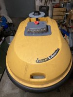
ROBOMOW RL1000 Rebuild
- Ersteller bernard
- Erstellt am
Hi b-tronic,Hi,
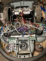
at the Moment I modify my RL1000 with the GPS system and a docking station.
I have changed the Sunray firmware to work with the Robomow.
If you need some help, just ask.
I plan to modify my RL2000 with PCB1.4 and GPS, which additional hardware do you use? GrandCentral M4, or still Arduino-Board?
May you can help me to find the best setup for me? ;-)
Thank you.
Daniel
Hi,
i use the GrandCentral, 3 INA226, 3 IBT Driver , the Odo solution with the hall sensors and a self build 10Ah Lion battery.
I modified the ESP32 software to control the mower over mqtt with openhab.
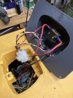
At the moment i am working on the charging station.
Do you have a 3d printer ?
I use a lot of part from Bernard and some others (GPS antenna holder, RTK solder plate case, ESP32 case, ESP32 external antenna, Mower control panel...
Regards B-Tronic
i use the GrandCentral, 3 INA226, 3 IBT Driver , the Odo solution with the hall sensors and a self build 10Ah Lion battery.
I modified the ESP32 software to control the mower over mqtt with openhab.
At the moment i am working on the charging station.
Do you have a 3d printer ?
I use a lot of part from Bernard and some others (GPS antenna holder, RTK solder plate case, ESP32 case, ESP32 external antenna, Mower control panel...
Regards B-Tronic
Thanks b-tronic for this while.Hi,
i use the GrandCentral, 3 INA226, 3 IBT Driver , the Odo solution with the hall sensors and a self build 10Ah Lion battery.
I modified the ESP32 software to control the mower over mqtt with openhab.
At the moment i am working on the charging station.
Do you have a 3d printer ?
I use a lot of part from Bernard and some others (GPS antenna holder, RTK solder plate case, ESP32 case, ESP32 external antenna, Mower control panel...
Regards B-Tronic
I think I will have more questions later on ;-)
Hi b-tronic,Hi,
i use the GrandCentral, 3 INA226, 3 IBT Driver , the Odo solution with the hall sensors and a self build 10Ah Lion battery.
I modified the ESP32 software to control the mower over mqtt with openhab.
At the moment i am working on the charging station.
Do you have a 3d printer ?
I use a lot of part from Bernard and some others (GPS antenna holder, RTK solder plate case, ESP32 case, ESP32 external antenna, Mower control panel...
Regards B-Tronic
how is the integration of the 3 mower motors in sunray? Is it possible to read all the currents and secure the board from overload? May you can share your modified sunray FW?
best regards
Daniel
Henrik Laursen
New member
Hi can you send me the STL for the hall sensor and magnet mount. ? Or guide me to where to finde them.I changed now to Odo Sensors into Hall sensors with 12 magnets.
Now, in my case the signal is much more better. When i do the Odo test, the wheels stop very exactly, before when i did the 5 turn test it was always different.
Just watch:
Anhang anzeigen 347Anhang anzeigen 348Anhang anzeigen 349
Thank you very much for your template.
Anhang anzeigen 346
 I will be happy to have alle the STL for robomow
For odometry
The last version use KY003 with 24 magnet mount in North South opposite F3d and stl are here:

 github.com

And some video and picture.
Do not forget to remove original robomow magnet.

Anhang anzeigen odo magnet.mp4
The last version use KY003 with 24 magnet mount in North South opposite F3d and stl are here:
AzuritBer/f3d file at robomowgy87 · Boilevin/AzuritBer
Ardumower full odometry version. Contribute to Boilevin/AzuritBer development by creating an account on GitHub.
github.com
AZDelivery KY-003 digitaler Hall Effekt Sensor Transistor | eBay
Les meilleures offres pour AZDelivery KY-003 digitaler Hall Effekt Sensor Transistor sont sur eBay ✓ Comparez les prix et les spécificités des produits neufs et d'occasion ✓ Pleins d'articles en livraison gratuite!
www.ebay.fr
And some video and picture.
Do not forget to remove original robomow magnet.
Anhang anzeigen odo magnet.mp4
Henrik Laursen
New member
Hi Bernard
thanks for the quick and accurate reply. it's nice to be able to ask and that someone bothers to answer.
I'll probably ask other questions. hope that is not too much trouble
the parts have already been ordered and I need to get the printer up and running soon")
I already have one more question. what is the reason for using 3 pcs IBT-2 H-Bridge is one not enough ??
thanks in advance / best regards
Henrik Laursen
thanks for the quick and accurate reply. it's nice to be able to ask and that someone bothers to answer.
I'll probably ask other questions. hope that is not too much trouble
the parts have already been ordered and I need to get the printer up and running soon
I already have one more question. what is the reason for using 3 pcs IBT-2 H-Bridge is one not enough ??
thanks in advance / best regards
Henrik Laursen
In working condition It's better to control the sense of individual motor in case one is totaly blocked by a piece of wood for example. It's avoid smoke and destroy one motor, but for test you can use only one driver .I already have one more question. what is the reason for using 3 pcs IBT-2 H-Bridge is one not enough ??
I don't use sunray ,so i can't help on RTK part ,certainly @b-tronic can ! but the hardware is normaly OK
Tinker
Member
Hi b-tronic,The pattern of the RL500 wheels is very plain. Poor grip.
This is my solution:
I'm new in this group and I want to pimp my RL500 with the GPS kit, still waiting for the necessary components. I have two pieces of the Robomower (one as a spare part supplier), so I have one RL500 running while the other one will be updated. Because I have also those problems with the wheels, I want to ask you for the stl file of your solution. Is there a download place? This would really help me and I thank you in advance!
Cheers
Tinker
Member
Hi Bernard,For odometry
The last version use KY003 with 24 magnet mount in North South opposite F3d and stl are here:
AzuritBer/f3d file at robomowgy87 · Boilevin/AzuritBer
Ardumower full odometry version. Contribute to Boilevin/AzuritBer development by creating an account on GitHub.
AZDelivery KY-003 digitaler Hall Effekt Sensor Transistor | eBay
Les meilleures offres pour AZDelivery KY-003 digitaler Hall Effekt Sensor Transistor sont sur eBay ✓ Comparez les prix et les spécificités des produits neufs et d'occasion ✓ Pleins d'articles en livraison gratuite!www.ebay.fr
And some video and picture.
Do not forget to remove original robomow magnet.
Anhang anzeigen 3567
Anhang anzeigen 3566
May I ask you how you got the magnetic disk on the motor axis. I don't have a plan right now :-( Can you please give me a hint?
Best regards
Mario
Addition:
I think found a solution. It probably only works if you “lever” the entire engine block unit with the gearbox out of the housing. After loosening the drive gear you have enough space to install the magnet wheel.
Zuletzt bearbeitet:
Exactly. You need to disassemble the gearbox.I think found a solution. It probably only works if you “lever” the entire engine block unit with the gearbox out of the housing. After loosening the drive gear you have enough space to install the magnet wheel.
here the link to 3d file.
AzuritBer/f3d file at robomowgy87 · Boilevin/AzuritBer
Ardumower full odometry version. Contribute to Boilevin/AzuritBer development by creating an account on GitHub.
github.com
Tinker
Member
Hi,
The days are slowly getting longer again, the grass is already growing a bit and it won't be long before I can finally test my Ardu/Robomower (RL 500 Base) in the wild.
I still have one problem (for now!): The Robomower has 2 balancing weights at the front to compensate for the weight of the originally heavy lead battery. Since I have replaced the battery with lithium cells, of course, I no longer need this compensation and this also makes the Ardu/Robomower lighter and easier to handle. But I just can't manage to remove these two weights in a simple way and I suspect that they are clamped on their plastic holder by tabs. Now I have seen that you Bernard have removed these 2 weights. How did you manage to do that? Did you have to remove (cut off) the plastic holder? I would be very happy to receive an answer from you!
By the way, I would like to thank you Bernard and b-tropic for your helpful contributions to the forum! Without them I would never have managed the Ardumower Sunray conversion. Un grand merci!
Mario
Anhänge
YesDid you have to remove (cut off) the plastic holder?
In my case i also add a weight (only one dead lead acid battery 12V7ah) inside the battery pack to have a better traction of the wheel but it's according your grass and mowing area.
Here the STL file to print the stopper.