Hi.
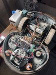
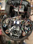
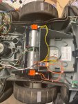
Here a PCB1.3,Pi zero,3.5 Inch Screen,Rfid reader Inside Robomow chassis.
Only tested for 5 or 6 hours with no particular issue.


The video test
Anhang anzeigen docking2_Trim.mp4
Anhang anzeigen lane mowing.Mp4
Anhang anzeigen random mowing.Mp4
Anhang anzeigen wire mowing.Mp4
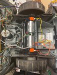
Here a PCB1.3,Pi zero,3.5 Inch Screen,Rfid reader Inside Robomow chassis.
Only tested for 5 or 6 hours with no particular issue.
The video test
Anhang anzeigen docking2_Trim.mp4
Anhang anzeigen lane mowing.Mp4
Anhang anzeigen random mowing.Mp4
Anhang anzeigen wire mowing.Mp4
Zuletzt bearbeitet:


") )
)