Du verwendest einen veralteten Browser. Es ist möglich, dass diese oder andere Websites nicht korrekt angezeigt werden.
Du solltest ein Upgrade durchführen oder einen alternativen Browser verwenden.
Du solltest ein Upgrade durchführen oder einen alternativen Browser verwenden.
ROBOMOW RL1000 Rebuild
- Ersteller bernard
- Erstellt am

I forget to put the Piardumower folder into robomow branch.
Now it's fix.
First Check the config.py
Use python idle and start Piardu3523.py to check there is no error into shell.
If it's ok save it as Piardu.py and use mower.sh to have the autostart on Power up
But , If you Don't have a SPI 3.5 inch screen, maybe you can test code from RFID branch Piardu217.py the 5 inch display version
I have actualy change the PiZero by a Pi3B+ and 3.5inch SPI display because i have issue with video and WIFI management on PiZero.
But the result is not very good the SPI display use many ressource from Pi and 5 inch HDMI run really faster.
Futur config is 5 Inch HDMI Screen,Pi3B+,PiCamera But need again more work on the towel to have all these parts in place (They work on my Denna platform)
I have a 3.5 display, but you are right, small and slow.
Do you have a link for the hdmi Display?
About the gyro:
I have done the calibration, but I have problems with the compass.
When I do the test, the position for north and other directions is always msg different.
Please tell me the right way to setup the compass, because I didn’t found a discription for the compass calibration.

Neu Display für Raspberry Pi 3/ 2/ B+ 3.5'' bis 7'' LCD HDMI Touch Screen DE eb | eBay
Les meilleures offres pour Neu Display für Raspberry Pi 3/ 2/ B+ 3.5'' bis 7'' LCD HDMI Touch Screen DE eb sont sur eBay ✓ Comparez les prix et les spécificités des produits neufs et d'occasion ✓ Pleins d'articles en livraison gratuite!
www.ebay.fr


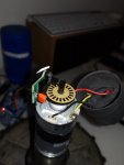
For GY87.
The GYRO calibration is very easy
Into Arduremote /Setting/IMU/Accel GYRO 30 sec calibration.
Click And wait max 2 3 minutes, the result is show into Arduino Ide console or PI according to your setting
The Compass calibration need strenght for robomow because it is very heavy.
Into Arduremote /Setting/IMU/Compass Cal start stop
Click one time
Smal bip are send and new data are coming in console
Move the mower
 arround all axis the most possible until no new bip or data in console.
Click again and you can see the save message.
Restart the mower.
Check the Gyro into setting IMU Pitch and roll by lift mower front ot right Wheel.
Pitch and roll near 0 when mower stop ,If no the GYRO calibration is not OK
For the compass the data you can see in arduremote can be Strange and not according with GYRO but it's better to do a real mowing test.
If all is OK when the mower start to mow :It stop, roll slowly and adjust the compas and Gyro heading.
If it roll more than 2 full revolution the Compass calibration is not OK.
Zuletzt bearbeitet:
I changed now to Odo Sensors into Hall sensors with 12 magnets.
Now, in my case the signal is much more better. When i do the Odo test, the wheels stop very exactly, before when i did the 5 turn test it was always different.
Just watch:


Thank you very much for your template.
Anhang anzeigen IMG_3690.MOV
Now, in my case the signal is much more better. When i do the Odo test, the wheels stop very exactly, before when i did the 5 turn test it was always different.
Just watch:
Thank you very much for your template.
Anhang anzeigen IMG_3690.MOV
Perfect I have the same result with the IR sensor.But the first Marotronics kit i use also fail to work correctly,second one was OK.
What is the sensor ref and how did you connect them to PCB1.3 ?
Maybe you can send me the STL file via private message to add them on GitHub.
What about the wheel addon ??
What is the sensor ref and how did you connect them to PCB1.3 ?
Maybe you can send me the STL file via private message to add them on GitHub.
What about the wheel addon ??

The rfid reader is locate under the battery pack.
Be carreful that the first version of the box with cover is not perfectly waterproof and i destroy the rfid reader.
So now i use only the box (You can stop the 3d print to have the correct high or modify the 3D file), fix the PN5180 with 2 screw and fill the box with candle wax so all the part is totally waterproof and the reader work well.


For MQTT
Yes it work perfectly (only tested with HASSIO) if you have WIFI in your garden.
You need to use all the code locate into RFID branch ,except inside DUE the ardumower code from robomowGY87 branch.
Do not forget to activate in into config.py and setup correctly the IP adress.
Be carreful that the first version of the box with cover is not perfectly waterproof and i destroy the rfid reader.
So now i use only the box (You can stop the 3d print to have the correct high or modify the 3D file), fix the PN5180 with 2 screw and fill the box with candle wax so all the part is totally waterproof and the reader work well.
For MQTT
Yes it work perfectly (only tested with HASSIO) if you have WIFI in your garden.
You need to use all the code locate into RFID branch ,except inside DUE the ardumower code from robomowGY87 branch.
Do not forget to activate in into config.py and setup correctly the IP adress.
To connect the RFID reader and ESP32 i have build and order PCB at JLCPCB.
It's 2 Eur for 5 boards if you have never already order.The same board is also use to build a low cost communicating sender.
You need to use the online editor easyeda and the file join to see and order the PCB.

It's 2 Eur for 5 boards if you have never already order.The same board is also use to build a low cost communicating sender.
You need to use the online editor easyeda and the file join to see and order the PCB.
Anhänge
i also have two broken IR sensors to count rpm on wheel robomow rs, by default they dont have a histerezis and generate too much fake extra pulses
however, the solution here worked perfectly: https://androminarobot.blogspot.com/2016/04/tutorial-sobre-el-encoder-fotoelectrico.html, by adding a 100nF capacitor between gnd and out
however, the solution here worked perfectly: https://androminarobot.blogspot.com/2016/04/tutorial-sobre-el-encoder-fotoelectrico.html, by adding a 100nF capacitor between gnd and out
Anhänge
Hi Bernard,
My RL1000 just died, and I am considering to convert it to Ardumower like you guys did. Looks like a fun winter project...
What battery are you using now? And how long can it mow on 1 charge?
Did you consider to reuse the original battery of the RL1000?
My wife always complained about the noise the RL1000 makes. Did you experiment with reducing the RPM of the mowers to reduce the noise?
In the paste i change The lead acid original battery each 2 years, so i decide to not reuse leadacid .
I build my own one using 18650 and china BMS, I don't remember but i thing it's 3*2600mah so 7800 AH .
All work actualy on 1200 m2 and 3 area for the summer without issue (near 300 Hours)
1 Charge mow betwween 1 and 3 hours according the high of the grass.
For the noise (It's not perfect with this platform and 5 motors) but the mowing motor PWM can modulate from 150 to 255 and in this case only the drive motor make noise when grass is low.
You need to check first if the mecanic parts is in good condition (gear box and mow motor) and check the final price including battery, PCB,time etc.....
.I build my own one using 18650 and china BMS, I don't remember but i thing it's 3*2600mah so 7800 AH .
All work actualy on 1200 m2 and 3 area for the summer without issue (near 300 Hours)
1 Charge mow betwween 1 and 3 hours according the high of the grass.
For the noise (It's not perfect with this platform and 5 motors) but the mowing motor PWM can modulate from 150 to 255 and in this case only the drive motor make noise when grass is low.
You need to check first if the mecanic parts is in good condition (gear box and mow motor) and check the final price including battery, PCB,time
etc.....Hello,
I have a project to rebuild an old MI555C (RL2000), Is it possible to use your same system bernard ? I have few questions. Congratulation for your fantastic work with azurbitber ! I Want to install the same system without rfid, because i have only one area easy to mow. I want to use the original sender ardumower (https://www.marotronics.de/Carte-em...tteur-de-boucle-de-tondeuse-a-gazon-robotique), is it possible with your software ? For the imu what is the best between GY87 or GY88 ? where do you buy the GY88, there's no in the shop marotronics. I see you change the R100 resistor by a R010, where can i buy this part, i search but don't find this.
Sorry for all the questions !
Do you have access to 3D printer ?
I have also rebuild RL2000, so no problem and use actually GY87 inside my RL1000 and RL2000.
When order a GY-87 you need to be sure it's not china copy (MPU6050 and HMC5883L are mandatory inside)
Maybe marotronics new arrival ?
GY-87 10DOF MPU6050 Sensor HMC5883L BMP180 Module GY87 | eBay
RFID and Raspberry are optional, so no problem.
Yes it work with marotronics sender but the WIFI version is cheaper.
Resistor:
WFMA2512R0100FEA | Résistance CMS 0.01Ω ±1%, série WFM, boitier 2512 (6432M) 3W, ±110ppm/°C | RS Components (rs-online.com)
Be carreful that i use now a new version of odometry kit with magnet like B-tronics suggest (IR is more tricky to adjust)
Azdelivery ky-003 numérique Hall Effet Capteur Transistor pour Arduino | eBay
and 72 magnet 3x2
Aimant Neodyme DISQUE Rond Fort Puissant Neodimum Magnet Photo Fimo Scrapbooking | eBay
Magnet are mount in North South opposition to have high frequency perfect result, so 32 magnet on each wheel result in 16 ticks per rev.

Anhang anzeigen odo magnet.mp4
I have also rebuild RL2000, so no problem and use actually GY87 inside my RL1000 and RL2000.
When order a GY-87 you need to be sure it's not china copy (MPU6050 and HMC5883L are mandatory inside)
Maybe marotronics new arrival ?
GY-87 10DOF MPU6050 Sensor HMC5883L BMP180 Module GY87 | eBay
RFID and Raspberry are optional, so no problem.
Yes it work with marotronics sender but the WIFI version is cheaper.
Resistor:
WFMA2512R0100FEA | Résistance CMS 0.01Ω ±1%, série WFM, boitier 2512 (6432M) 3W, ±110ppm/°C | RS Components (rs-online.com)
Be carreful that i use now a new version of odometry kit with magnet like B-tronics suggest (IR is more tricky to adjust)
Azdelivery ky-003 numérique Hall Effet Capteur Transistor pour Arduino | eBay
and 72 magnet 3x2
Aimant Neodyme DISQUE Rond Fort Puissant Neodimum Magnet Photo Fimo Scrapbooking | eBay
Magnet are mount in North South opposition to have high frequency perfect result, so 32 magnet on each wheel result in 16 ticks per rev.
Anhang anzeigen odo magnet.mp4
Yes i have access to a 3D printer.
In a second time i wish add a raspberry to work with Jeedom and to add a camera (and maybe a screen).
For the odometer it’s a very good idea for the magnets in alternance north and south ! Is it possible to have the file for print the pieces (wheel and support) please ?
In a second time i wish add a raspberry to work with Jeedom and to add a camera (and maybe a screen).
For the odometer it’s a very good idea for the magnets in alternance north and south ! Is it possible to have the file for print the pieces (wheel and support) please ?
File are now locate on Github:Yes i have access to a 3D printer.
In a second time i wish add a raspberry to work with Jeedom and to add a camera (and maybe a screen).
For the odometer it’s a very good idea for the magnets in alternance north and south ! Is it possible to have the file for print the pieces (wheel and support) please ?
AzuritBer/f3d file at robomowgy87 · Boilevin/AzuritBer (github.com)