Du verwendest einen veralteten Browser. Es ist möglich, dass diese oder andere Websites nicht korrekt angezeigt werden.
Du solltest ein Upgrade durchführen oder einen alternativen Browser verwenden.
Du solltest ein Upgrade durchführen oder einen alternativen Browser verwenden.
ArduMower Brushless Drive
- Ersteller BerndS
- Erstellt am
Ja, Verkabelung wäre noch mal was für den WIKI - Eintrag.
Ein Bug fix scheint es auch noch zu geben.
WIKI Brushless
Ein Bug fix scheint es auch noch zu geben.
WIKI Brushless
spranz
Active member
Danke für eure Hilfe,
leider hatte ich einen Fehler in der Verkabelung und nun geht nichts mehr.
Ich habe einen neuen Thread aufgemacht, damit wir hier nicht zu weit vom Thema abweichen.
Vielleicht hat noch jemand einen Tipp für mich?
https://forum.ardumower.de/threads/...uche-dringen-hilfe-bei-der-fehlersuche.24178/
leider hatte ich einen Fehler in der Verkabelung und nun geht nichts mehr.
Ich habe einen neuen Thread aufgemacht, damit wir hier nicht zu weit vom Thema abweichen.
Vielleicht hat noch jemand einen Tipp für mich?
https://forum.ardumower.de/threads/...uche-dringen-hilfe-bei-der-fehlersuche.24178/
Hello,
I have built an Ardomower last year and am very impressed. Fantastic work! I have some further needs (6400 m2 croquet lawn with green quality and a large garden) and am looking into building two mowers:
A) Reel mower for green grass (5 mm) using one John Deere ECut220 reel unit. 48V motors
B) A mower for normal grass but with three mower motors. 24V motors
I am rather new to electronics, but have been coding C# and some C++ for 15 years. Would be very glad for some help. I understand German well, but don’t write so well. I have ordered the BL board and DIY brushless driver from the shop. I have the PCB 1.3 with Adafruit M4 and will order the PCB 1.4 when available.
Brushless questions:
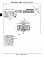
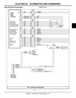
The John Deere cutting unit has a BLDC motor. See attached schematics. I am not entirely sure of the power, but according to specifications the alternator provides 25-30A depending on version and 48V. I assume 30A as peek power.
1. The specifications (attached) show motor input A, B, C and hall sensor output C-A, B-C, A-B. All drivers I have seen have U,V,W for both input and hall sensor output. In which order shall C-A, B-C and A-B be connected to a driver?
2. The specification show 12V VCC for the hall sensors. I tried with the ACT Motors 8015A driver (5V) to see if I could get the motor to rotate without load. I got a little vibration and then the driver burnt. Do I need a driver with 12V hall sensor feed? Where can I find a working driver which can work with the Ardumover BL board?
- Is the BL board using 0-5V or PWM for speed control?
3. I have ordered a few motors for testing and prototyping both mower A (48V 400W with wormgear for driving) and mower B (24V for mower and driver, 50-100W). What do I need to do to use the ACT Motors 8015A (and similar) with the BL board and Ardumower?
4. What is the best way to connect three mower motors to PCB 1.3 (or 1.4) (with BL drive motors also)?
Best,
Anton
Anhänge
Zuletzt bearbeitet:
Bernd,Hello Anton;
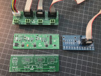
I have done several tests with the ACT 8015A Controller and developed special Adapter for that. My first Version worked with the ACT driver.
But I can't say if this is working with the JD motor
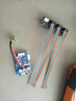
Anhang anzeigen 2177
The ACT controller is too small for the JohnDeere motor (48V, ca 30A). (I tried the ACT Controller and it burnt). I am not entirely sure of the specifications and have ordered a 4 channel oscilloscope to measure the motor with the existing JohnDeere controller. And then finding an appropriate new controller. Again, I am rather new to electronics and having a bit of learning to do.
The ACT Motors controller should be fine for the wheel motors however. 48V and 400W. I would be very happy to try out the controller you have built and for a suitable payment?
Best,
Anton
Anton my controller is working up to 8Amps only. If the ACT burns, it must be more than 40Amps the JD Motor needs. My design / controller can be modified with stronger MOSFETs, but this will cost several hundred euro to develop. So I think it is better you find a suitable controller in the internet or adapt the original JD controller.
Starsurfer78
Active member
Perhaps the Maytech SUPERFOC 6.8 would be the right for that.
50A continuous current and 240A peak
50A continuous current and 240A peak
Of course, thanks. I will try to find a controller which have the same specifications as the ACT controller. So that I can use two ACT controllers for the wheel motors and one similar for the JD motor.Anton my controller is working up to 8Amps only. If the ACT burns, it must be more than 40Amps the JD Motor needs. My design / controller can be modified with stronger MOSFETs, but this will cost several hundred euro to develop. So I think it is better you find a suitable controller in the internet or adapt the original JD controller.
Does the Ardumower Brushless Adapter in the Marotronics shop work with the ACT controller? Is it PWM or 0-5V used for the AVI port on the ACT? Are there additional coding changes required for using ACT instead of the DIY Brushless driver?
Hi @bernard,
yes MotorBRK is the brake, but this is not supported by the PCB1.x. MotorAVI are the HAL Ticks provided by the DRV8308. This is the Signal I send to the Odo Divider on PCB1.x. The act. Boards is limited to 3.5A and max32V. If you want to user more powerful motors you have to change e.g main fuse current limiter resistor. The MOSFETs can provide 8A / 15A pik.
You can use this signal directly (5V TTL Level) but then you do not have the current measurement. This IC is on the adapter board.
But I'm just working on a CAN controller for the driver, to manages the driver via CAN-Bus. HW for CAN is running already SW takes a while.....
Perfekt, danke
