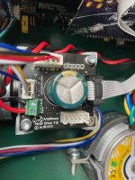
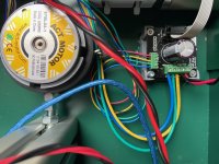
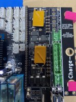
ArduMower Brushless Drive

Meines Wissens hat @markus 3D Druckfile.
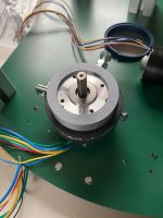
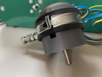
Ich habe schnell einen Adapter für den brushless Mähermotor erstellt und gedruckt (siehe Design unter https://www.tinkercad.com/things/6cRtNzGHEsl-ardumower-mowing-motor-chassis-adaptor), damit ich weiterbauen konnte :). Ich denke, es ist sehr nah an dem Adapter, den ich auf einem Bild im Wiki gesehen habe (https://wiki.ardumower.de/index.php?title=Datei:Bldc_pcb_holder_example.jpg).

Vielen Dank auch für die sehr nützlichen PCB holder für die brushless Motoren (Download über https://wiki.ardumower.de/index.php?title=DIY_Brushless_Driver_Board). Sehr schön.

ps: meine muttersprache ist nicht deutsch, daher übersetze ich das mit google translate. Entschuldigung für komische Sätze :cool:
 

Anhänge

  • IMG_1249.jpeg
    IMG_1249.jpeg
    251,1 KB · Aufrufe: 34
  • IMG_1248.jpeg
    IMG_1248.jpeg
    263,9 KB · Aufrufe: 32
  • IMG_1250.jpeg
    IMG_1250.jpeg
    362,2 KB · Aufrufe: 35
Hallo JohanB, hast du dir auch die Motorhalter oder nur die Platinenhalter gedruckt. Ich finde das man die Brushless Antriebsmotoren nicht einfach so frei reinhängen sollte.
 
Hallo JohanB, hast du dir auch die Motorhalter oder nur die Platinenhalter gedruckt. Ich finde das man die Brushless Antriebsmotoren nicht einfach so frei reinhängen sollte.
Ich habe nur die Platinenhalter gedruckt. Das sind die einzigen Designs, die ich gefunden habe. Ich habe mich auch gefragt, ob die Motoren nicht besser zusätzliche Unterstützung hätten; vielleicht etwas für später.

ps: Ich verstehe, dass Ihnen auch Teile gefehlt haben (z. B. esp32). Hast du schon eine Antwort? Ich habe E-Mails an den Shop geschickt, aber noch nichts gehört.
 
Ich hatte gestern mit Markus telefonisch gesprochen und er sagte mir das heute ein Paket kommt mit den fehlenden Teilen ich hoffe das dann alles dabei ist. Da auch mir das ESP32 fehlt und auch noch ein paar andere Dinge. Eine Woche musst du ihm ungefähr Zeit lassen. Er hat so viele Aufträge.
Und es wird ein neuer Motorhalter entwickelt. Mal sehen was sich da noch alles tut.
 
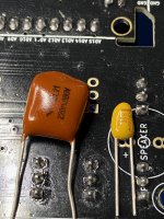
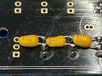
Frage zum Bugfix mit den 200nF Kondensatoren für das Brushless Adapterboard v1.0. Wie ist die Polaritätsausrichtung der Kondensatoren? Meine 220-nF-Tantal-Kondensatoren sind polarisiert, aber ich sehe keinen Hinweis auf die Polarität an den Odometrie-Pins.
 
200nF Kondensatoren sind normalerweise keine Tantals, bist du sicher dass das nicht uF sind?
GND / - ist der Mittelkontakt des 3 Pol. JST Steckers.
Mach mal bitte ein Foto von den Kondensatoren.
 

Anhänge

  • IMG_1276.jpeg
    IMG_1276.jpeg
    1,9 MB · Aufrufe: 17
Zuletzt bearbeitet:
It is not necessary; you can also use only one GND connection. I have pre-configured cable / plugs so I removed only one. It is also more robust
 
It is not necessary; you can also use only one GND connection. I have pre-configured cable / plugs so I removed only one. It is also more robust
Danke!
I thought I did not understand something ;-) I still need to make that more robust cable but since I just soldered the EF2 fuse again, I want to give the motors a try. Or can I just leave out the connection for the odometry all together for testing the motors?

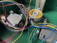
I have found no error in my cabling since last time I did the test and fried the fuse and the mosfet though :-( I attached pictures, maybe someone can spot a mistake?

I think I may have mis-plugged the power cable by 1 pin on the main board on that test, which effectively reverses the polarity to the motor, but I cannot be sure. I see no other mistake in my cabling. I also verified if the fuses under the brushless adaptor do not touch the adapter, and double checked all wires.

Feeling a bit nervous trying to test again...

Edit: please note that the last picture (IMG_1283) shows the EF2 removed and bypassed to test the board while waiting for the new SMD fuse. The picture was taken before I soldered a new fuse to test the motors ;-)
 

Anhänge

  • IMG_1286.jpeg
    IMG_1286.jpeg
    337,6 KB · Aufrufe: 54
  • IMG_1282.jpg
    IMG_1282.jpg
    253,8 KB · Aufrufe: 49
  • IMG_1280.jpeg
    IMG_1280.jpeg
    335,3 KB · Aufrufe: 47
  • IMG_1278.jpeg
    IMG_1278.jpeg
    347,7 KB · Aufrufe: 56
  • IMG_1283.jpeg
    IMG_1283.jpeg
    435,8 KB · Aufrufe: 56
Zuletzt bearbeitet:
Just tested the motors. Worked perfectly!
So I think I just misplugged the power lines for one motor by 1 pin. 🤦‍♂️
I now just covered the pins I do not need between the left and right motor power connectors on the main board. Making that same mistake again is not possible anymore.
 
One of my brushless propulsion motors have burned, I dont know why. But can not find any ordering details on it, or in the shop. Can anyone help me with this?
 
Hallo, Ich habe gerade meinen Mower mit dem Komplett-Kit Chassis 2021 mit GPS-RTK und BL-Motoren zusammenbgebaut. Die erste Testfahrt lief gut. Auch der Mähmotor lief. Nach 1 Tag startet der Mäher nicht mehr. Ich habe einmal die Serielle Ausgabe des Central M4 angeschaut. Das Board stoppt beim Hochlauf mit einem Fehler Mähmotor, der auch bei Wiederholungen immer wieder Auftritt. Der Fehler ist nicht näher beschrieben.
Kann mir jemand sagen, wie ich das Problem angehen kann?
 
Hier der Screenshot. Temperaturmodul und IMU sind nicht eingebaut, daher unplausible Werte dort.
 

Anhänge

  • Screenshot Mow-Motor-Fehler.png
    Screenshot Mow-Motor-Fehler.png
    71,9 KB · Aufrufe: 36
Oben