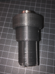
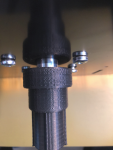
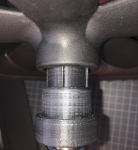
my ArduMower, we call him Rüdiger ;-)

I think Bernard suggestions are very good.
I agree with Bernard, that the board should be as simple as possible. The simpler the board is, the better and cheaper it is.
Also if you have hardware problems it is easier to find. Using modules has also the advantage for troubleshooting. I think not all
people are able to replace a defective smd part or have deep know how in electronics.
When you design a new board, you should improve it.
If you have to adapt the software, you can make a branch change that, test it and make a pull request.


My comments to Bernards suggestions:

The Odo divisor : It's better to not include it in the board (leave the user adjust with addon card if necessary or replace the motor ODO sensor)
=> The divisor was brought in because the Mega were not able to handle the interrupts (by the way the intteruptroutine was too long also). So it is not needed. And I personally hated it since the PCB1.3 came out. In Raindancer I had to undo that by running the interrupt on the positve and negative flank. Furthermore the current divisor design produces spikes. Therefore you should put in a filter to filter out that spikes.

The watchdog : Arduino Due include a hardware watchdog and it's work perfectly, so you don't need it.
=> Yes that is right. I think the Metro has also a watchdog.

The I2C line : one TCA9548A can replace all the SMD Component,simplify the board trace and is really easy to manage using the code.
=> There is some more advantage of that chip: Debugging the I2C bus and finding errors is much easier. I also would use an external module and not solder it on the board. Important is, that one can connect 5V or 3.3V to a port. Also think about that the Metro has no pull ups build in.

The current sensing : Again I2C external INA219 work perfectly and require 0 pin on Due
=> Using it as module also. The only thing here is that it needs more time to read it out compared to an analog in.

The perimeter receiver : i agree with you (maybe no need voltage divisor) because on my scope i never see more than 2.5Volt on this line, but need ROLAND confirmation.
=>I use a 1H coil to get a better signal. I realised at the border that the signal can swap from inside to outside or the other way arround if the signal ist too strong. The reason for that is the uneven distribution of the signal. I fixed that situation in the Raindancer code. But after I put in a voltage divider I hadn't that problem anymore. You can also substract 0.85V from the perimeter signal by hardware to bring it in the middle to 1.65V. Maybe that is a better solution.

The RTC : a DS3231 is 3.3V module, have eeprom and is more robust than the actual RTC, so again include it on the board reduce trace complexity.
=> Agree. The current RTC Module is a pain in the ass.

The Power line : I don't understand all perfectly but we need the power off from DUE and the PCB1.3 heat a lot, so :unsure:
=> I don't understand.

The charging line : Leave the charger and BMS on battery do the job.
=>Thats right. My problem is I bought a battery and don't know what function the BMS which is build in has. I bought that battery:
https://www.batteryupgrade.de/shopBrowser.php?assortmentProductId=77464674&shopGroupId=86427148 which have a build in BMS. But I don't know if it only do loadbalancing or also undervoltage protection.

The Serial line : Not sure you need voltage divisor (Actual peripheral work in 3.3V RPI,GPS,ESP32 etc) or maybe on only one serial port.
=> maybe it's not bad to have a choice between 5V and 3.3V.

So PCB Lite include connector for mandatory DS3231,TCA9548A and all other connector are for external board like motor driver and sensor
=> Also using external modules is better for replacing parts if they break and error finding.


Nachtrag: Ich habe gerade gesehen, dass an den TXB0102DCUR VCCA und VCCB keine 100nF Kondensatoren angeschlossen sind.
 
Zuletzt bearbeitet:
Wow, thanks @roland and @bernard for this huge input and discussions.

So you convinced me, we will build a modern Mower Board with new, modern components.
I think this is not a light Version, but it will be smaller and more crisp.

But let’s finish the Brushless Board, compatible to V1.3, first.

@bernard , I checked the clock and I think DS3231 is much better than DS1307 and it seems address and register compatible (for the common DS1307 functions).
So we can use the clock on this BL-Mower Board.
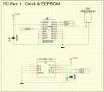
@roland, I deleted the AT24C32 EEPROM and will spend a AT24C256 EEPROM, it is cheaper and maybe we find some more data we can store.
So here is the rework of the Clock & EEPROM Part, this can also be the firdt Part for the light Board :

1601146090705.png
 
Hi @roland ;
Found some time to look deeper in your feedback. Thanks, that helps to have a sparing partner 😊

Here my remarks:

Step down :
XL4015 DC 36V/5A or the smaller LM2596S 40V/3A


Missing voltagedivider 5V->3.3V before Perimeter Left/Right :
I can’t see a voltage divider in V1.3 schematic. Is that something I missed? On my V1.3 board I do not have one.


PCB1.3 RX and TX at the Due connector are mixed up. That is an error:
I fixed this and con Tx->RX and RX<-TX.

Describe connections to K58.
Here you can add additional switches or signals to stop the Motors.. Just to give the user the Brake functionality. I use it to stop the motors during reset. Sometimes during reset I see movements of the motors.

Connect Free Ports that the input can not be floating:
What ports do you mean?

"must cut the conductor" => better DipSwitches.
Yes, if I have the space for them.

Voltagedivider after ACS720 has an output of 4.17V at 5V
Sorry, no. He makes 100mv/A that mean 2V for 20A. That mean may. 4,5V / 3,75V aver divider.
But I don’t think that someone uses relay 20 Amps, the Plugs are fot 8Amps. So 10A. should be the max.


ACS720 1uF not needed. Only at PeakDetection circiute as I remember:
I see some High and low peaks; I assume during coil switching. So the 1uF should stable this to an average,

Reserve AD10 is real AnlalogIn. Don't waste it.
Reserve ADC13 is the DAC at the DUE
Better use pins which are not used on the PCB1.3.
I will check if there are some others….

Maybe it is a good idea to disable Leds with a dip switch. If the mower is running nobody needs that and it saves energy.
Yes but the space 😊

The charging relay on PCB1.3 produces a little heat. Maybe that is not so bad when it is cold outside and wet in the early morning.
I need it not longer. This has been replaced by IC 14 BTS443P MOSFET Switch.

I will have a look into the oter feedbacks, specialy in @bernard s and update the schematics and poste it here.
 
Maybe i misunderstood but when i tell you the DS3231 it was the full board
including battery and eeprom and not only the chips.
You need only to change the i2c adress in the code
I use it in the past with TCS9548A and PCB1.2 for 2 or 3 month without any issue.

Same for TCA9548A
I try to find the old azurit code for TCA9548 management .

Also ESP32 DEV KIT can easily replace the old HC05 BT module (AND can manage WIFI and BT) so again 3.3V, so you don't need component on PCB connect directly Due Serial1 line to ESP32 Serial2 line and a 10 line code is enought for a full compatibility With AZURIT, so the WLAN port ??
ESP32 is also usefull to build a low cost WIFI sender (Not possible with ESP8266)
 
I find the code for TCA9548A and it was very easy to manage, a simple void into driver.cpp:
Code:
void tca9548PortSelect(uint8_t i) {  //select the port for i2c multiplexer
  if (i > 7) return;
  Wire.beginTransmission(TCA9548_ADDRESS);
  Wire.write(1 << i);
  Wire.endTransmission(); 
}
and you can select the port that you want to use in the main loop with
tca9548PortSelect(2);

This 2017 October code use 3 HMC5883 compass with same I2C adress //GY801 on port 3 / RTC on port 2 / GY87 on port 1 / CompassGps on port 0
and show that it's not a good idea to use a COMPASS near motor or electronics :LOL::LOL::LOL::LOL::LOL:
 

Anhänge

  • AZURIT TCA9548A.zip
    158,2 KB · Aufrufe: 6
Hi Bernd,

thanks for the information. I think using DS3231 and AT24C256 is very good because the DS1307 was very inaccurate.
I wrote: "If you have to adapt the software, you can make a branch change that, test it and make a pull request."
Maybe that is wrong. Because I can't say if Alexander agrees code, that is not for the PCB1.3 and their system.

"Voltagedivider after ACS720 has an output of 4.17V at 5V
Sorry, no. He makes 100mv/A that mean 2V for 20A. That mean may. 4,5V / 3,75V aver divider.
But I don’t think that someone uses relay 20 Amps, the Plugs are fot 8Amps. So 10A. should be the max."

Ok, I didn't know, that you want to use 20A sensors. To handle a worst case scenario, it is maybe a good idea then to protect the sense ports at the due with diodes like the other ports?

"Describe connections to K58.
Here you can add additional switches or signals to stop the Motors.. Just to give the user the Brake functionality. I use it to stop the motors during reset. Sometimes during reset I see movements of the motors."

I realised that also. Currently I disable the motordrivers with the enable signal directly after the Setup starts. And at the end of the Setup, I enable the drivers. On the desk it works very well. But I have no running chassis yet.

"Connect Free Ports that the input can not be floating:"

On page 4 you have some free parts where the input is not connected. It could be, that the inputs are foating and then changes the output with high frequency. To prevent that the inputs should be coneccted to GND or what ever, so that they are fixed.


One question I have. What was the reason for the selection of TXB0102? The TXB0102 are not able to handle pullups. You use it for all levelshifting. That could be a problem. If you would use the TXS0102 you were much more conform with the PCB1.3 (I think).

https://www.ti.com/lit/ds/symlink/txs0102.pdf?ts=1601217160893&ref_url=https%3A%2F%2Fwww.ti.com%2Fproduct%2FTXS0102%3Futm_source%3Dgoogle%26utm_medium%3Dcpc%26utm_campaign%3Dhval-null-null-GPN_EN-cpc-pf-google-eu%26utm_content%3DTXS0102%26ds_k%3DTXS0102%26DCM%3Dyes%26gclid%3DCjwKCAjw8MD7BRArEiwAGZsrBUkp3CvzjTBbDhfMfrBXBAUXy6dRQXMLdAUnStgPZXZ0fuVLxshpwhoCNbMQAvD_BwE%26gclsrc%3Daw.ds


One further remark: You put 3V at the dropsensor but connect it to the 5V levelshifter output. Is that correct? Originally the drop sensor was connected to 5V.


And the last remark:

I read for the MAX706 the following: "The watchdog
function for the MAX706P/R/S/T can not be disabled. The
watchdog timer for the MAX706AP/AR/AS/AT disables when
WDI input is left open or connected to a tri-state output"

Did you selected the right chip that the WDI could let unconnected through J1? I could not find that
 
Zuletzt bearbeitet:
Hallo,
mein Vorschlag: Arduino Due ersetzen durch Teensy4.1.
Das Board ist immer noch Arduino-IDE compatible, die Software-Anpassungen sind aus meiner Sicht zu bewältigen, die Rechenleistung und die Schnittstellen liegen auf einem ganz anderen Nieveau.
Wenn man die Elektronik schon neu macht, dann gleich mit einem merklichen Upgrade in der Rechnerperfomance. Natürlich gibt es Interesse das pcb1.3 weiter zu bedienen - das sind die gekannten Herausforderungen bei der Rückwärtscompatibilität.
Gruß Fürst Ruprecht
 
Hallo @Fürst Ruprecht, das Problem ist nicht die Rechenleistung da ist der Due noch nicht überfordert. Aber mit dem Sunray kommt er mit dem Speicher an seine Grenzen und kann nicht sovoel Kartendaten laden. Aber es gibt bereite eine bessere CPU für den Ardumower, mehr Speichen, SD Karte, Baugleich zum Due und vor allem, das Board wird schon von Sunray unterstützt.
siehe hier:
 
Ja, ich habe mir das angesehen und anschließend einige Tage nach einer Möglichkeit fürs "Aufbohren" gesucht.
Ich habe mir alle/viele Prozessoren/Generationen angesehen, insbesondere unter dem Aspekt mein vorhandenes pcb1.3 (Anzahl der IOs) und arduino-ide zu nutzen.
Mein Fazit ist nach der Recherche der Teensy4.1 .
Es gibt noch eine 3-Kern-Boardvariante mit arduino-Sockel, die jedoch schon wegen des Preises von >100€ aus dem Rennen fällt.
Der teensy hat aus meiner Sicht nur einen Nachteil - er benötigt für die Menge der digitalen-IOs nach meiner Rechnung 1-2 Portmultiplexer(16-Kanal). Der Rest ist fast schon überproportioniert. Flash- und/oder Ram-Erweiterung ist auf der Platine vorgesehen, SD-Kartenslot vorhanden.

Aber das könnt Ihr ja auch alles nachlesen unter

Den Grand Central habe ich bestellt, der teensy liegt bereits hier.
Meine nächsten Schritte -> Grand Central in Betrieb nehmen, über teensy->pcb1.3 Adapter nachdenken.
Allerdings muß man sagen, daß der teensy von den Programmiermöglichkeiten/Anfoderungen auch eine andere Nummer ist.


Gruß Fürst Ruprecht
 
Ja, das Board hat schon was und hat eine deutlich höhere Performance. Aber wofür? Wenn der Due schon nicht ausgelastet ist dann idelt der Teensy4.1 im mover doch nur rumm, Ich finde da die akt. Lösung eigentlich schon genial, den Arduino als Controller für den Mover und alles andere über den RasPi und über Apps die zB. die Karten generieren.
 
Ich will defintiv nicht meckern, es ist nicht böse gemeint und ich will keinem auf die Füße treten.

Grundsätzlich bin ich der erste der "hier" schreit wenn es was neues gibt oder man die Möglichkeit der Verbesserung hat. Und sobald es eine funktionierende brushlessversion gibt, werde ich die bestellen (egal bei wem). Persönlich finde ich es auch gut wenn eine Platine überarbeitet wird und an aktuelle Entwicklungen angepasst wird; ebenso beim Chassi.
Bei dem vorhandenem PCB ist es so, das die Daten frei zugänglich sind; jeder hat die Möglichkeit entweder bei @markus zu bestellen oder eben selber zu fräsen/sägen/lasern oder was auch immer. Dein Chassi macht netterweise dein Kumpel, wie schaut es aus mit Rechnung, Zuverlässigkeit, Haftung usw?

Die Zukunft des Ardumowers wird sicherlich in sunray liegen; schleifenmäher bekommt man mitlerweile in jedem Baumarkt hinter her geworfen. Du steckst jetzt viel Arbeit, Energie & Ideen in eine neue PCB; wie schaut es aus mit der kompatibilität zu sunray? Alleine der Umstieg vom due zum m4 hat @greymfm76 einiges an Zeit abverlangt um es "mal eben" zu integrieren.

Ich denke auch das jedem von uns bewusst ist, das die PCB im Shop keine €90,- in der Herstellung kostet. Aber mit den "Gewinnen" werden auch die Kosten für Entwicklung, Reklamationen, Gewährleistung, Weiterentwicklung und und und gedeckt. Es ist afaik auch das einzige Teil welches nicht wo anders erworben werden kann. Da Geiz geil ist, suchen Kunden immer wo sie nen Taster, Stecker, Netzteil usw für ein paar Cent weniger bekommen; eine hardwareseitige Refinanzierung des Projekts erfolgt also auch über die PCB.

Du siehst wie viel positives Feedback und Aufrufe der Thread bekommt, was in der Folge auch bedeutet das immer mehr sagen "das will ich auch" und damit werden Alexander & Markus gezwungen zu reagieren; und das ist meistens eine für alle unschöne Situation.

Ich würde eher dahin tendieren das man eine derartige Neuentwicklung in einen geschlossenen Bereich verlegt. Dann können SW-Entwicklung, Shop, HW-Entwicklung vernünftig zusammen arbeiten und am ende etwas entwickeln was eine in allen Punkten eine Verbesserung darstellt.
 
Hallo @holunder ;
keep calm.....
Seit dem Wochenende bin ich von Alexander in genau diese Gruppe eingeladen. Wir diskutieren gerade ziemlich wild was machbar wäre, vor allem rund um den BL Antrieb, natürlich und vor allem für die existierenden Ardumower aber auch Neues.
Die Ideen und Anregungen die von euch kommen sind schon klasse und helfen. Es heißt aber nicht dass das in neue Board übernommen werden kann.
Auch rede ich, wenn ich @bernard s Idee nach einem light Board aufgreife von einem Experiment, das noch fern einer Massenfertigung ist.
Und sollte sowas in den Markt kommen können, wird das sicher in Kooperation mit Markus geschehen......
ABER, wenn neue HW kommt, muß da vor allem Alexander sein letztes Wort geben, dass das die SW unterstützt.
Also, Du siehst, alles ist gut. Aber danke für die mahneneden Worte.
 
Na ja, ich fange langsam an mich zu fragen, ob das hier die ausgelagerte Entwicklungsabteilung für einen Online-shop und einen Softwareentwickler ist.
Wenn ein User sein eigenes Ding entwickelt und hier zur Diskussion stellt, unterliegt er aus meiner Sicht keinen Regeln oder Verpflichtungen. Wenn hier eine Kompatibilität für eine Software gefordert/gewünscht wird, dann ist es höchste Zeit, daß einmal geklärt wird, was der Sinn dieses Forums überhaupt sein soll.
Wer bestimmt denn die Richtung der Software/Hardware? Unter welchen Gesichtpunkten findet das statt? Sunray drängt sich aus meiner Sicht hier etwas zu stark in den Vordergrund. Wenn die Hardware ausgerichtet wird auf die Software eines Softwareentwicklers, der seinen Lebensunterhalt bestreiten muß, wie wird dann die Zukunft aussehen? Azurite wurde anscheinend nicht kommerzialisiert.

Wenn der Sinn des Forums letztlich der Kommerzialisierung und der Weiterentwicklung der Produkte Software und Hardware aus dem Online-shop dienen soll, dann solltet Ihr das Forum anders gestalten.
Wenn ein Beitrag wie dieser in Kürze so viel Zuspruch bekommt, dann könnt Ihr doch froh sein, daß Ihr das "Kundenfeedback" hier direkt mitbekommt.
Ich würde mir dann auch Gedanken machen, ob meine/eure Ausrichtung optimal ist.
Ich sehe mal von der rechtlichen Seite ganz ab, aber klar ist schon, daß Ideengeber/Mitentwickler deren Lösungen einfließen oder die einen Lösungsweg vorwegnehmen einen Beteiligungsanspruch an der Vermarktung haben und das unabhängig von Risiko, etc..
Damit wären wir dann bei dem Thema Neugestaltung des Forums angekommen.

Bernard,
Aus meiner Sicht ist der Ardumower nur für Bastler geeignet, allein vom technischen Anspruch und den Kosten her.
Zur Sunray-Software kann ich nichts sagen, jedoch stehen die finanziellen Aufwendungen beim User zum Realnutzen, verglichen mit anderen Lösungen nicht besonders gut. (in Zukunft kommen möglicherweise noch Kosten für die App dazu).
Natürlich ist teensy bei gleichzeitiger Nutzung von Due, raspi und Handy überdimmensioniert. Dann würde ich zuerst den Raspi in Frage stellen.

Wäre das ein Forum ohne kommerzielle Weiterverwertung, dann wäre das sowieso egal, Hauptsache es macht Spaß, ein Blumenstrauß an Lösungen ermöglicht die individuelle Gestaltung des eigenen Projektes - aber ???

Gruß Fürst Ruprecht
 
Sunray drängt sich aus meiner Sicht hier etwas zu stark in den Vordergrund.
naja, es ist halt die Zukunft. Sehe ich zumindest so. Glaube kaum das irgendeiner freiwillig die Schlefe verlegt und die FW funktioniert wirklich sehr gut.
Wenn die Hardware ausgerichtet wird auf die Software eines Softwareentwicklers, der seinen Lebensunterhalt bestreiten muß, wie wird dann die Zukunft aussehen? Azurite wurde anscheinend nicht kommerzialisiert.
@BerndS ist doch nicht verpflichtet seine selbst entwickelte Hardware auf Sunray auszurichten. Wenn User das wünschen ist es seine Entscheidung ob er den Wünschen nachkommt oder nicht. Abgesehen davon würde Bernd selber ganz gerne Sunray verwenden.
Wenn das Bord dann irgendwann mal bei Markus im Shop landet wird bestimmt ein Teil des Erlöses für weitere Entwicklung benötigt und auch Bernd wird vielleicht für seine Arbeit ein Stück weit entlohnt woranich auch nichts schlimmes finde solange die Kirche im Dorf bleibt.
Hauptsache es macht Spaß, ein Blumenstrauß an Lösungen ermöglicht die individuelle Gestaltung des eigenen Projektes - aber ???
Natürlich ist so eine Vielfalt an Entwicklungen schön, hat aber auch den Nachteil das alles nicht 100% ausgereift ist, halt von Allem ein bisschen.
Wenn es 10 verschiedenen PCBs gibt bleibt der normale User, z.B. ich, schon bei der Wahl des PCBs hängen. Viele Lösungen verkomplizieren auch viel. Und schrecken auch viele ab. Dementsprechend weniger User und es bleibt ein Projekt für einen kleinen Zirkel mit wenig Entwicklungsmöglichkeiten.

Das ist alles meine Meinung und ich will keinen damit persönlich angreifen.
 
kermi, das hast Du schön geschrieben, da gibts nix dran auszusetzen.
Ob es die Zukunft ist, hängt am Ende wesentlich von den Kosten, dem Aufwand und der Zuverlässigkeit ab.
Die hardware für Bilderkennung kostet nur ein Bruchteil und bietet im Vergleich zu GPS neben der reinen Position weitere Möglichkeiten. Hier findet grundsätzlich sehr viel Entwicklungsleistung statt. Wenn man für 5€ bereits Gesichter erkennen kann ...
-> ich wollte ja Rasen-Verkehrsschilder aufstellen, aber die Kamera hat sich nicht einlernen lassen - schade.
Na, wir werden sehen.

Gruß Fürst Ruprecht
 
Ja, preislich ist der Ardumover schon etwas weiter oben angesiedelt ... zumindest im Vergleich zum 300€ Baumarkt-Mäher und Bilderkennung wird wohl auch irgendwann mal dem RTK-Mäher überlegen sein., die Zukunft wird es zeigen.
Vielleicht kann auch der Ardumover irgendwann mal Bilderkennung. Es wäre schön wenn die Entwicklung immer weiter geht, ich finde das ganze Projekt wahnsinnig toll.
 
preislich ist der Ardumover schon etwas weiter oben angesiedelt ... zumindest im Vergleich zum 300€ Baumarkt-Mäher
Da möchte ich dir widersprechen. Er ist sicher in der Anschaffung teurer, aber auf seine Lebenszeit und die Wartung und Reparatur, die man selbst machen kann ist er preiswerter als jeder Marken-Mower und in der Lebenszeit des Ardumower und seinen Verbesserungsmöglichkeiten überlebt der 3-4 Baumarkt Rasenroboter.
Ich bin hier gelandet weil gerade die Wartungskosten an meinem jetzigen Mäher alle 2 Jahre locker 200-300 € sind. Kohlen tauschen defekte Motoren, Akku etc..
Mittlerweile habe ich da soviel Geld investiert, da könnte ich schon einen guten High End Roboter von kaufen, das macht aber keinen Spaß :)
Und ja wie Du schreibst, ich mach mein Ding so wie ich glaube dass es am besten ist. Und richtig ist m.E. mit dem Team an einem Strang zu ziehen um die wenigen Ressourcen auf neue Funktionen zu fokussieren und nicht konkurrierende HW anzubieten. Auch bin ich nicht erpicht einen Shop o.ä. aufzubauen, weil ich dazu keinen Bock habe.

Und jetzt bitte wieder zurück auf das eigentliche Thema.
 
Hallo Comunity;
es ist ja in einigen Beiträgen nach den Rädern gefragt worden die @phoenix_83 und ich verwenden.
Auf der 1. Seite dieses Beitrags habe ich ja meine Radachse als 3d Model und als 3d Druckdatei eingestellt.
Hier mal ein paar Fotos wie ich die Achse gebaut habe.
In das 3 D Druckteil verklebe ich eine 65-67mm mm lange Alu oder Edelstahlhülse, die auf die Getriebewelle passt.
Durchmesser der Hülse, außen 18 mm, innen auf 14,5mm aufgebohrt.
1601401978963.png
1601402062818.png
1601402121707.png
 
Zuletzt bearbeitet:
Oben