I think Bernard suggestions are very good.
I agree with Bernard, that the board should be as simple as possible. The simpler the board is, the better and cheaper it is.
Also if you have hardware problems it is easier to find. Using modules has also the advantage for troubleshooting. I think not all
people are able to replace a defective smd part or have deep know how in electronics.
When you design a new board, you should improve it.
If you have to adapt the software, you can make a branch change that, test it and make a pull request.
My comments to Bernards suggestions:
The Odo divisor : It's better to not include it in the board (leave the user adjust with addon card if necessary or replace the motor ODO sensor)
=> The divisor was brought in because the Mega were not able to handle the interrupts (by the way the intteruptroutine was too long also). So it is not needed. And I personally hated it since the PCB1.3 came out. In Raindancer I had to undo that by running the interrupt on the positve and negative flank. Furthermore the current divisor design produces spikes. Therefore you should put in a filter to filter out that spikes.
The watchdog : Arduino Due include a hardware watchdog and it's work perfectly, so you don't need it.
=> Yes that is right. I think the Metro has also a watchdog.
The I2C line : one TCA9548A can replace all the SMD Component,simplify the board trace and is really easy to manage using the code.
=> There is some more advantage of that chip: Debugging the I2C bus and finding errors is much easier. I also would use an external module and not solder it on the board. Important is, that one can connect 5V or 3.3V to a port. Also think about that the Metro has no pull ups build in.
The current sensing : Again I2C external INA219 work perfectly and require 0 pin on Due
=> Using it as module also. The only thing here is that it needs more time to read it out compared to an analog in.
The perimeter receiver : i agree with you (maybe no need voltage divisor) because on my scope i never see more than 2.5Volt on this line, but need ROLAND confirmation.
=>I use a 1H coil to get a better signal. I realised at the border that the signal can swap from inside to outside or the other way arround if the signal ist too strong. The reason for that is the uneven distribution of the signal. I fixed that situation in the Raindancer code. But after I put in a voltage divider I hadn't that problem anymore. You can also substract 0.85V from the perimeter signal by hardware to bring it in the middle to 1.65V. Maybe that is a better solution.
The RTC : a DS3231 is 3.3V module, have eeprom and is more robust than the actual RTC, so again include it on the board reduce trace complexity.
=> Agree. The current RTC Module is a pain in the ass.
The Power line : I don't understand all perfectly but we need the power off from DUE and the PCB1.3 heat a lot, so
=> I don't understand.
The charging line : Leave the charger and BMS on battery do the job.
=>Thats right. My problem is I bought a battery and don't know what function the BMS which is build in has. I bought that battery:
https://www.batteryupgrade.de/shopBrowser.php?assortmentProductId=77464674&shopGroupId=86427148 which have a build in BMS. But I don't know if it only do loadbalancing or also undervoltage protection.
The Serial line : Not sure you need voltage divisor (Actual peripheral work in 3.3V RPI,GPS,ESP32 etc) or maybe on only one serial port.
=> maybe it's not bad to have a choice between 5V and 3.3V.
So PCB Lite include connector for mandatory DS3231,TCA9548A and all other connector are for external board like motor driver and sensor
=> Also using external modules is better for replacing parts if they break and error finding.
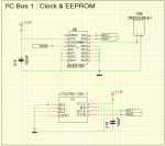
Nachtrag: Ich habe gerade gesehen, dass an den TXB0102DCUR VCCA und VCCB keine 100nF Kondensatoren angeschlossen sind.
I agree with Bernard, that the board should be as simple as possible. The simpler the board is, the better and cheaper it is.
Also if you have hardware problems it is easier to find. Using modules has also the advantage for troubleshooting. I think not all
people are able to replace a defective smd part or have deep know how in electronics.
When you design a new board, you should improve it.
If you have to adapt the software, you can make a branch change that, test it and make a pull request.
My comments to Bernards suggestions:
The Odo divisor : It's better to not include it in the board (leave the user adjust with addon card if necessary or replace the motor ODO sensor)
=> The divisor was brought in because the Mega were not able to handle the interrupts (by the way the intteruptroutine was too long also). So it is not needed. And I personally hated it since the PCB1.3 came out. In Raindancer I had to undo that by running the interrupt on the positve and negative flank. Furthermore the current divisor design produces spikes. Therefore you should put in a filter to filter out that spikes.
The watchdog : Arduino Due include a hardware watchdog and it's work perfectly, so you don't need it.
=> Yes that is right. I think the Metro has also a watchdog.
The I2C line : one TCA9548A can replace all the SMD Component,simplify the board trace and is really easy to manage using the code.
=> There is some more advantage of that chip: Debugging the I2C bus and finding errors is much easier. I also would use an external module and not solder it on the board. Important is, that one can connect 5V or 3.3V to a port. Also think about that the Metro has no pull ups build in.
The current sensing : Again I2C external INA219 work perfectly and require 0 pin on Due
=> Using it as module also. The only thing here is that it needs more time to read it out compared to an analog in.
The perimeter receiver : i agree with you (maybe no need voltage divisor) because on my scope i never see more than 2.5Volt on this line, but need ROLAND confirmation.
=>I use a 1H coil to get a better signal. I realised at the border that the signal can swap from inside to outside or the other way arround if the signal ist too strong. The reason for that is the uneven distribution of the signal. I fixed that situation in the Raindancer code. But after I put in a voltage divider I hadn't that problem anymore. You can also substract 0.85V from the perimeter signal by hardware to bring it in the middle to 1.65V. Maybe that is a better solution.
The RTC : a DS3231 is 3.3V module, have eeprom and is more robust than the actual RTC, so again include it on the board reduce trace complexity.
=> Agree. The current RTC Module is a pain in the ass.
The Power line : I don't understand all perfectly but we need the power off from DUE and the PCB1.3 heat a lot, so
=> I don't understand.
The charging line : Leave the charger and BMS on battery do the job.
=>Thats right. My problem is I bought a battery and don't know what function the BMS which is build in has. I bought that battery:
https://www.batteryupgrade.de/shopBrowser.php?assortmentProductId=77464674&shopGroupId=86427148 which have a build in BMS. But I don't know if it only do loadbalancing or also undervoltage protection.
The Serial line : Not sure you need voltage divisor (Actual peripheral work in 3.3V RPI,GPS,ESP32 etc) or maybe on only one serial port.
=> maybe it's not bad to have a choice between 5V and 3.3V.
So PCB Lite include connector for mandatory DS3231,TCA9548A and all other connector are for external board like motor driver and sensor
=> Also using external modules is better for replacing parts if they break and error finding.
Nachtrag: Ich habe gerade gesehen, dass an den TXB0102DCUR VCCA und VCCB keine 100nF Kondensatoren angeschlossen sind.
Zuletzt bearbeitet: