/*
Ardumower (www.ardumower.de)
Copyright (c) 2013-2015 by Alexander Grau
Copyright (c) 2013-2015 by Sven Gennat
Copyright (c) 2014 by Maxime Carpentieri
Copyright (c) 2015 by Uwe Zimprich
Copyright (c) 2015 by Frederic Goddeeres
Copyright (c) 2015 by Jürgen Lange
Private-use only! (you need to ask for a commercial-use)
This program is free software: you can redistribute it and/or modify
it under the terms of the GNU General Public License as published by
the Free Software Foundation, either version 3 of the License, or
(at your option) any later version.
This program is distributed in the hope that it will be useful,
but WITHOUT ANY WARRANTY; without even the implied warranty of
MERCHANTABILITY or FITNESS FOR A PARTICULAR PURPOSE. See the
GNU General Public License for more details.
You should have received a copy of the GNU General Public License
along with this program. If not, see <http://www.gnu.org/licenses/>.
Private-use only! (you need to ask for a commercial-use)
*/
///////////////////////////////////////////////////////////////////////////////////////
/*Terms of use
///////////////////////////////////////////////////////////////////////////////////////
//THE SOFTWARE IS PROVIDED "AS IS", WITHOUT WARRANTY OF ANY KIND, EXPRESS OR
//IMPLIED, INCLUDING BUT NOT LIMITED TO THE WARRANTIES OF MERCHANTABILITY,
//FITNESS FOR A PARTICULAR PURPOSE AND NONINFRINGEMENT. IN NO EVENT SHALL THE
//AUTHORS OR COPYRIGHT HOLDERS BE LIABLE FOR ANY CLAIM, DAMAGES OR OTHER
//LIABILITY, WHETHER IN AN ACTION OF CONTRACT, TORT OR OTHERWISE, ARISING FROM,
//OUT OF OR IN CONNECTION WITH THE SOFTWARE OR THE USE OR OTHER DEALINGS IN
//THE SOFTWARE.
///////////////////////////////////////////////////////////////////////////////////////
//Support
///////////////////////////////////////////////////////////////////////////////////////
Website: [URL]http://www.brokking.net/imu.html[/URL] Youtube: [URL]https://youtu.be/4BoIE8YQwM8[/URL] Version: 1.0 (May 5, 2016)
Version for Ardumower-I2C Display and Ardumower by J.L.
Website: [URL]http://www.ardumower.de[/URL] Hardware: BumperDuino or ArduBumperPerimeterDuino_V3.00.ABPD
IDE: Arduino 1.6.13
///////////////////////////////////////////////////////////////////////////////////////
*/
#include <avr/wdt.h>
#include <EEPROM.h>
//Include LCD and I2C library
#include <LiquidCrystal_I2C.h>
#include <Wire.h>
//Declaring some global variables
int eeAddressRoll = 1; //Location we want the data to be put.
int eeAddressPitch = 6; //Location we want the data to be put.
int gyro_x, gyro_y, gyro_z;
long acc_x, acc_y, acc_z, acc_total_vector;
int temperature;
long gyro_x_cal, gyro_y_cal, gyro_z_cal;
long loop_timer;
int lcd_loop_counter;
float angle_pitch, angle_roll;
int angle_pitch_buffer, angle_roll_buffer, AbsPitchErr, AbsRollErr;
int PrevAnglePitch, PrevAngleRoll;
int AbsDisasterAngle = 55; // Grad = Absolutely disaster angle
int RelDisasterAngle = 23 ; // Grad = Relatively disaster angle
int Max_Angular_Error = LOW;
int RelPitchErr = LOW , RelRollErr = LOW;
unsigned long RelDisasterTimer;
unsigned int RelDisasterTime = 700; // Timer in ms
boolean set_gyro_angles;
float angle_roll_acc, angle_pitch_acc;
float angle_roll_acc_cal, angle_pitch_acc_cal;
float angle_pitch_output, angle_roll_output;
int MPU_Setup = 0;
//////////////////////////////////////////////////////////////////////////////////////////////////////
//Initialize the LCD library
//LiquidCrystal_I2C lcd(0x27,16,2);
// addr, en,rw,rs,d4,d5,d6,d7
// LiquidCrystal_I2C lcd(0x27, 2, 1, 0, 4, 5, 6, 7); // Set the LCD I2C address
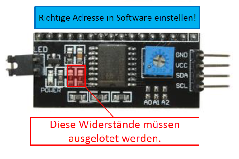
// The address pins A0-A2 are pulled high with the three 10k resistors at the bottom of the picture.
// If the three pads A0-A2 are jumpered, the address is changed to 0x20.
// [URL]https://bitbucket.org/fmalpartida/new-liquidcrystal/wiki/schematics#!i2c-connection[/URL] // Set the pins on the I2C chip used for LCD connections:
// Set the correct Address !!!!!!!!!!!!!!!!!!!!!!!!!!!!!!!!!!!!!!!!!!!!!!!!!!!!!!!!
// addr, en,rw,rs,d4,d5,d6,d7,bl,blpol
//LiquidCrystal_I2C lcd(0x3F, 2, 1, 0, 4, 5, 6, 7); // Set the LCD I2C address at PCF8574AT
LiquidCrystal_I2C lcd(0x27, 2, 1, 0, 4, 5, 6, 7); // Set the LCD I2C address  at PCF8574T
//////////////////////////////////////////////////////////////////////////////////////////////////////
const int MPXPin1 = A0; // Analog input pin that the MPX5010 is attached to
const int MPXPin2 = A1; // Analog input pin that the MPX5010 is attached to
int MPXBase1 = 0; // Base number for comparison
int MPXDif1 = 0; // Difference result
int MPX1TriggerLevel = 3; // Lowest sensitivity for triggering
int MPXErr1 = LOW; // Notification of contact detected
int MPXBase2 = 0; //Base number for comparison
int MPXDif2 = 0; // Difference result
int MPX2TriggerLevel = 3; // Lowest sensitivity for triggering
int MPXErr2 = LOW; // Notification of contact detected
const long intervalBumper = 50; // Measuring speed (milliseconds)
unsigned long previousMillisBumper = 0;
int MPX1State = LOW; // Sequence control for measurement
int MPX2State = LOW; // Sequence control for measurement
int BumperState = LOW; // Sequence control for measurement
const int Button = 4;
const int BumperOutPin = 9;
const int TiltOutPin = 10;
const int Buzzer = 5;
const int LEDAngelErr = 3;
const int LEDBumperRightErr = 8;
const int LEDBumperLeftErr = 7;
const int LEDActive = 13;
const int LEDFault = 16;
const int LEDok = 17;
int LEDActiveState = LOW;
const long intervalLedActive = 500; // interval at which LED was blink (milliseconds)
unsigned long previousMillisLedActive = 0;
boolean debug = 0;
void setup() {
WatchDog_Setup();
pinMode(Button, INPUT_PULLUP);
pinMode(LEDActive, OUTPUT);
pinMode(LEDFault, OUTPUT);
pinMode(LEDok, OUTPUT);
pinMode(BumperOutPin, OUTPUT);
pinMode(TiltOutPin, OUTPUT);
pinMode(LEDAngelErr, OUTPUT);
pinMode(LEDBumperRightErr, OUTPUT);
pinMode(LEDBumperLeftErr, OUTPUT);
pinMode(Buzzer, OUTPUT);
Wire.begin(); //Start I2C as master
if (debug) Serial.begin(57600); //Use only for debug
int ButtonState = digitalRead(Button); // Push the button to setup MPU at the first use to calibrate the system
if (!ButtonState) {
angle_roll_acc_cal = 0.0;
angle_pitch_acc_cal = 0.0;
MPU_Setup = 1;
digitalWrite(LEDok, HIGH); //Indicates the system is ready to setup at this time
} else {
EEPROM.get(eeAddressRoll, angle_roll_acc_cal);
EEPROM.get(eeAddressPitch, angle_pitch_acc_cal);
}
digitalWrite(LEDActive, HIGH); //Set LED high to indicate startup
digitalWrite(LEDAngelErr, HIGH); //Set LED high to indicate startup
digitalWrite(LEDBumperRightErr, HIGH); //Set LED high to indicate startup
digitalWrite(LEDBumperLeftErr, HIGH); //Set LED high to indicate startup
digitalWrite(BumperOutPin, LOW);
//*********************************************************************************
// Set the output to high to indicate that the system is calibrating the gyroscope
// The system must stand still for this time
// This should not be a problem because the TILT output should shutdown all engines
// At the end of the calibration the output has to be set low
//*********************************************************************************
digitalWrite(TiltOutPin, HIGH);
setup_mpu_6050_registers(); //Setup the registers of the MPU-6050 (500dfs / +/-8g) and start the gyro
lcd.begin(16, 2); //Initialize the LCD
// Switch on the backlight
lcd.setBacklightPin(3, POSITIVE);
lcd.setBacklight(HIGH); //Activate backlight
lcd.clear(); //Clear the LCD
lcd.setCursor(0, 0); //Set the LCD cursor to position to position 0,0
lcd.print("Bumper-Duino V.3"); //Print text to screen
lcd.setCursor(0, 1); //Set the LCD cursor to position to position 0,1
lcd.print("ArduMower Sensor"); //Print text to screen
wdt_reset(); //Reset watchdog to prevent reset
delay(1500); //Delay 1.5 second to display the text
wdt_reset(); //Reset watchdog to prevent reset
lcd.clear(); //Clear the LCD
lcd.setCursor(2, 0); //Set the LCD cursor to position to position 0,0
lcd.print("MPU-6050 IMU"); //Print text to screen
lcd.setCursor(6, 1); //Set the LCD cursor to position to position 0,1
lcd.print("V1.5"); //Print text to screen
wdt_reset(); //Reset watchdog to prevent reset
delay(1500); //Delay 1.5 second to display the text
if (MPU_Setup) {
wdt_reset();
lcd.clear(); //Clear the LCD
lcd.setCursor(2, 0); //Set the LCD cursor to position to position 0,0
lcd.print("MPU-6050 IMU"); //Print text to screen
lcd.setCursor(3, 1); //Set the LCD cursor to position to position 0,1
lcd.print("Setup Mode"); //Print text to screen
wdt_reset(); //Reset watchdog to prevent reset
delay(1500);
}
wdt_reset(); //Reset watchdog to prevent reset
lcd.clear(); //Clear the LCD
lcd.setCursor(0, 0); //Set the LCD cursor to position to position 0,0
lcd.print("Calibrating gyro"); //Print text to screen
lcd.setCursor(0, 1); //Set the LCD cursor to position to position 0,1
for (int cal_int = 0; cal_int < 2000 ; cal_int ++) { //Run this code 2000 times
wdt_reset(); //Reset watchdog to prevent reset
if (cal_int % 125 == 0)lcd.print("."); //Print a dot on the LCD every 125 readings
read_mpu_6050_data(); //Read the raw acc and gyro data from the MPU-6050
gyro_x_cal += gyro_x; //Add the gyro x-axis offset to the gyro_x_cal variable
gyro_y_cal += gyro_y; //Add the gyro y-axis offset to the gyro_y_cal variable
gyro_z_cal += gyro_z; //Add the gyro z-axis offset to the gyro_z_cal variable
delay(3); //Delay 3us to simulate the 250Hz program loop
}
gyro_x_cal /= 2000; //Divide the gyro_x_cal variable by 2000 to get the avarage offset
gyro_y_cal /= 2000; //Divide the gyro_y_cal variable by 2000 to get the avarage offset
gyro_z_cal /= 2000; //Divide the gyro_z_cal variable by 2000 to get the avarage offset
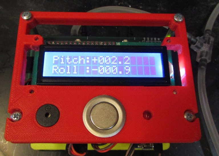
lcd.clear(); //Clear the LCD
lcd.setCursor(0, 0); //Set the LCD cursor to position to position 0,0
lcd.print("Pitch:"); //Print text to screen
lcd.setCursor(0, 1); //Set the LCD cursor to position to position 0,1
lcd.print("Roll :"); //Print text to screen
digitalWrite(LEDActive, LOW); //Set LED low to indicate startup finished
digitalWrite(LEDAngelErr, LOW); //Set LED low to indicate startup finished
digitalWrite(LEDBumperRightErr, LOW); //Set LED low to indicate startup finished
digitalWrite(LEDBumperLeftErr, LOW); //Set LED low to indicate startup finished
if (!MPU_Setup) digitalWrite(LEDok, HIGH); //Indicates the system is ready to go
loop_timer = micros(); //Reset the loop timer
RelDisasterTimer = millis();
digitalWrite(TiltOutPin, LOW); //Shows the end of calibration
wdt_reset(); //Reset watchdog to prevent reset
}
////////////////////////////////////////////////////////////////////////////////////////////////////////////////////////////////////////////////////////
/////////////////////////////////////////////////////////////// Main Loop //////////////////////////////////////////////////////////////////////////////
////////////////////////////////////////////////////////////////////////////////////////////////////////////////////////////////////////////////////////
void loop() {
wdt_reset(); //Reset watchdog to prevent reset
// ----------------------------------------- mS Timer for measurement interval -----
unsigned long currentMillis = millis();
// --------------------------------------------------------------------------------
// ----------------------------------------------- active LED blink ---------------
if (currentMillis - previousMillisLedActive >= intervalLedActive)
{
previousMillisLedActive = currentMillis;
if (LEDActiveState == LOW) {
LEDActiveState = HIGH;
}
else
LEDActiveState = LOW;
// set the LED with the ledState of the variable:
digitalWrite(LEDActive, LEDActiveState);
if (MPU_Setup) digitalWrite(LEDok, LEDActiveState); //Indicates the system is in setup mode
else digitalWrite(LEDok, HIGH); //Indicates the system is ready to go
}
////////////////////////////////////////////////////////////////////////////////////////////////////////////////////////////////////////////////////////
// BBBBB U U M M PPPPP EEEEEEE RRRRRR
// B B U U MM MM P P E R R
// BBBBBB U U M M M M PPPPP EEEEE RRRRRR
// B B U U M M M P E R R
// BBBBBB UUUUU M M P EEEEEEE R R
///////////////////////////////////////1/////////////////////////////////////////////////////////////////////////////////////////////////////////////////
if (currentMillis - previousMillisBumper >= intervalBumper) // It is time to read out Bumper value?
{
previousMillisBumper = currentMillis; // Safe the current time
if (BumperState == LOW) { // Who should be read bumper 1 or 2
BumperState = HIGH; // In next reading read bumper 2
if (MPX1State == LOW) { // Read the base or read the difference
MPX1State = HIGH; // In next reading read the difference
MPXBase1 = analogRead(MPXPin1); // Read the base
MPXDif1 = 0; // Set the difference for output to zero
MPXErr1 = LOW; // No notification of contact detected
} else { // Read the base or read the difference. Read the difference
MPXDif1 = analogRead(MPXPin1); // Read the value for difference
if (MPXDif1 > MPXBase1) { // Check whether the value of the difference is greater
MPXDif1 = MPXDif1 - MPXBase1; // Calculate difference
if (MPXDif1 >= MPX1TriggerLevel) { // The difference is greater than the trigger ?
MPXErr1 = HIGH; // Notification of contact detected
MPX1State = HIGH; // Read next difference levle
} else { // Difference was no longer greater
MPX1State = LOW; // No notification of contact detected
MPXDif1 = 0; // Set the difference for output to zero
}
} else { // Difference was not greater
MPXDif1 = 0; // Set the difference for output to zero
MPX1State = LOW; // No notification of contact detected
}
}
} else { // Who should be read bumper 1 or 2. Read Bumper 2
BumperState = LOW;
if (MPX2State == LOW) { // Read the base or read the difference
MPX2State = HIGH; // In next reading read the difference
MPXBase2 = analogRead(MPXPin2); // Read the base
MPXDif2 = 0; // Set the difference for output to zero
MPXErr2 = LOW; // No notification of contact detected
} else { // Read the base or read the difference. Read the difference
MPXDif2 = analogRead(MPXPin2); // Read the value for difference
if (MPXDif2 > MPXBase2) { // Check whether the value of the difference is greater
MPXDif2 = MPXDif2 - MPXBase2; // Calculate difference
if (MPXDif2 >= MPX2TriggerLevel) { // The difference is greater than the trigger ?
MPXErr2 = HIGH; // Notification of contact detected
MPX2State = HIGH; // Read next difference levle
} else { // Difference was no longer greater
MPX2State = LOW; // No notification of contact detected
MPXDif2 = 0; // Set the difference for output to zero
}
} else { // Difference was not greater
MPXDif2 = 0; // Set the difference for output to zero
MPX2State = LOW; // No notification of contact detected
}
}
}
}
////////////////////////////////////////////////////////////////////////////////////////////////////////////////////////////////////////////////////////
// M M PPPPP U U
// MM MM P P U U
// M M M M PPPPP U U
// M M M P U U
// M M P UUUUU
////////////////////////////////////////////////////////////////////////////////////////////////////////////////////////////////////////////////////////
read_mpu_6050_data(); //Read the raw acc and gyro data from the MPU-6050
gyro_x -= gyro_x_cal; //Subtract the offset calibration value from the raw gyro_x value
gyro_y -= gyro_y_cal; //Subtract the offset calibration value from the raw gyro_y value
gyro_z -= gyro_z_cal; //Subtract the offset calibration value from the raw gyro_z value
//Gyro angle calculations
//0.0000611 = 1 / (250Hz / 65.5)
angle_pitch += gyro_x * 0.0000611; //Calculate the traveled pitch angle and add this to the angle_pitch variable
angle_roll += gyro_y * 0.0000611; //Calculate the traveled roll angle and add this to the angle_roll variable
//0.000001066 = 0.0000611 * (3.142(PI) / 180degr) The Arduino sin function is in radians
angle_pitch += angle_roll * sin(gyro_z * 0.000001066); //If the IMU has yawed transfer the roll angle to the pitch angel
angle_roll -= angle_pitch * sin(gyro_z * 0.000001066); //If the IMU has yawed transfer the pitch angle to the roll angel
//Accelerometer angle calculations
acc_total_vector = sqrt((acc_x * acc_x) + (acc_y * acc_y) + (acc_z * acc_z)); //Calculate the total accelerometer vector
//57.296 = 1 / (3.142 / 180) The Arduino asin function is in radians
angle_pitch_acc = asin((float)acc_y / acc_total_vector) * 57.296; //Calculate the pitch angle
angle_roll_acc = asin((float)acc_x / acc_total_vector) * -57.296; //Calculate the roll angle
//----------------------------------------------------------------------------------------------
//Set the MPU-6050 Setup spirit level in the following two lines for calibration
angle_pitch_acc -= angle_pitch_acc_cal; //Accelerometer calibration value for pitch
angle_roll_acc -= angle_roll_acc_cal; //Accelerometer calibration value for roll
//----------------------------------------------------------------------------------------------
if (set_gyro_angles) { //If the IMU is already started
angle_pitch = angle_pitch * 0.9996 + angle_pitch_acc * 0.0004; //Correct the drift of the gyro pitch angle with the accelerometer pitch angle
angle_roll = angle_roll * 0.9996 + angle_roll_acc * 0.0004; //Correct the drift of the gyro roll angle with the accelerometer roll angle
}
else { //At first start
angle_pitch = angle_pitch_acc; //Set the gyro pitch angle equal to the accelerometer pitch angle
angle_roll = angle_roll_acc; //Set the gyro roll angle equal to the accelerometer roll angle
}
//To dampen the pitch and roll angles a complementary filter is used
angle_pitch_output = angle_pitch_output * 0.9 + angle_pitch * 0.1; //Take 90% of the output pitch value and add 10% of the raw pitch value
angle_roll_output = angle_roll_output * 0.9 + angle_roll * 0.1; //Take 90% of the output roll value and add 10% of the raw roll value
if (!set_gyro_angles) {
PrevAnglePitch = angle_pitch_output * 10;
PrevAngleRoll = angle_roll_output * 10;
set_gyro_angles = true; //Set the IMU started flag
} else {
int ButtonState = digitalRead(Button);
if (MPU_Setup == 1 && !ButtonState) { //MPU_Setup == 1 &&
angle_pitch_acc_cal = angle_pitch_output;
angle_roll_acc_cal = angle_roll_output;
//One simple call, with the address first and the object second.
EEPROM.put(eeAddressPitch, angle_pitch_output);
EEPROM.put(eeAddressRoll, angle_roll_output);
MPU_Setup = 0;
}
}
write_LCD_and_Output(); //Write the roll and pitch values to the LCD display and to the outputs
while (micros() - loop_timer < 4000); //Wait until the loop_timer reaches 4000us (250Hz) before starting the next loop
loop_timer = micros(); //Reset the loop timer
}
////////////////////////////////////////////////////////////////////////////////////////////////////////////////////////////////////////////////////////
////////////////////////////////////////////////////////////////////////////////////////////////////////////////////////////////////////////////////////
////////////////////////////////////////////////////////////////////////////////////////////////////////////////////////////////////////////////////////
void read_mpu_6050_data() { //Subroutine for reading the raw gyro and accelerometer data
Wire.beginTransmission(0x68); //Start communicating with the MPU-6050
Wire.write(0x3B); //Send the requested starting register
Wire.endTransmission(); //End the transmission
Wire.requestFrom(0x68, 14); //Request 14 bytes from the MPU-6050
while (Wire.available() < 14); //Wait until all the bytes are received
acc_x = Wire.read() << 8 | Wire.read(); //Add the low and high byte to the acc_x variable
acc_y = Wire.read() << 8 | Wire.read(); //Add the low and high byte to the acc_y variable
acc_z = Wire.read() << 8 | Wire.read(); //Add the low and high byte to the acc_z variable
temperature = Wire.read() << 8 | Wire.read(); //Add the low and high byte to the temperature variable
gyro_x = Wire.read() << 8 | Wire.read(); //Add the low and high byte to the gyro_x variable
gyro_y = Wire.read() << 8 | Wire.read(); //Add the low and high byte to the gyro_y variable
gyro_z = Wire.read() << 8 | Wire.read(); //Add the low and high byte to the gyro_z variable
}
////////////////////////////////////////////////////////////////////////////////////////////////////////////////////////////////////////////////////////
void write_LCD_and_Output() { //Subroutine for writing the LCD
//To get a 250Hz program loop (4us) it's only possible to write one character per loop
//Writing multiple characters is taking to much time
if (lcd_loop_counter == 17)lcd_loop_counter = 0; //Reset the counter after 14 characters
lcd_loop_counter ++; //Increase the counter
if (lcd_loop_counter == 1) {
angle_pitch_buffer = angle_pitch_output * 10; //Buffer the pitch angle because it will change
if (debug) {
if (angle_pitch_buffer < 0)Serial.print("-");
Serial.print(abs(angle_pitch_buffer) / 10);
Serial.print(" ");
}
lcd.setCursor(6, 0); //Set the LCD cursor to position to position 0,0
if ((abs(angle_pitch_buffer) / 10) >= AbsDisasterAngle) {
AbsPitchErr = HIGH;
}
else AbsPitchErr = LOW;
}
if (lcd_loop_counter == 2) {
if (angle_pitch_buffer < 0)lcd.print("-"); //Print - if value is negative
else lcd.print("+"); //Print + if value is negative
}
if (lcd_loop_counter == 3)lcd.print(abs(angle_pitch_buffer) / 1000); //Print first number
if (lcd_loop_counter == 4)lcd.print((abs(angle_pitch_buffer) / 100) % 10); //Print second number
if (lcd_loop_counter == 5)lcd.print((abs(angle_pitch_buffer) / 10) % 10); //Print third number
if (lcd_loop_counter == 6)lcd.print("."); //Print decimal point
if (lcd_loop_counter == 7)lcd.print(abs(angle_pitch_buffer) % 10); //Print decimal number
if (lcd_loop_counter == 8) {
angle_roll_buffer = angle_roll_output * 10; //Buffer the roll angle because it will change
if (debug) {
if (angle_roll_buffer < 0)Serial.print("-");
Serial.print(abs(angle_roll_buffer) / 10);
Serial.print(" ");
Serial.print(MPXDif1);
Serial.print(" ");
Serial.println(MPXDif2);
}
lcd.setCursor(6, 1);
if ((abs(angle_roll_buffer) / 10) >= AbsDisasterAngle) {
AbsRollErr = HIGH;
}
else AbsRollErr = LOW;
}
if (lcd_loop_counter == 9) {
if (angle_roll_buffer < 0)lcd.print("-"); //Print - if value is negative
else lcd.print("+"); //Print + if value is negative
}
if (lcd_loop_counter == 10)lcd.print(abs(angle_roll_buffer) / 1000); //Print first number
if (lcd_loop_counter == 11)lcd.print((abs(angle_roll_buffer) / 100) % 10); //Print second number
if (lcd_loop_counter == 12)lcd.print((abs(angle_roll_buffer) / 10) % 10); //Print third number
if (lcd_loop_counter == 13)lcd.print("."); //Print decimal point
if (lcd_loop_counter == 14)lcd.print(abs(angle_roll_buffer) % 10); //Print decimal number
if (lcd_loop_counter == 15) {
if (millis() >= RelDisasterTimer) {
RelDisasterTimer = millis() + RelDisasterTime;
if (((abs(angle_roll_buffer) / 10) - (abs(PrevAngleRoll) / 10)) >= RelDisasterAngle) {
RelRollErr = HIGH;
} else if (RelRollErr == HIGH && (abs(angle_roll_buffer) / 10) <= (abs(PrevAngleRoll) / 10)) {
RelRollErr = LOW;
} else if (!RelRollErr) {
PrevAngleRoll = angle_roll_buffer;
}
if ((abs(angle_pitch_buffer) / 10) - (abs(PrevAnglePitch) / 10) >= RelDisasterAngle) {
RelPitchErr = HIGH;
} else if (RelPitchErr == HIGH && (abs(angle_pitch_buffer) / 10) <= (abs(PrevAnglePitch) / 10)) {
RelPitchErr = LOW;
} else if (!RelPitchErr) {
PrevAnglePitch = angle_pitch_buffer;
}
if (RelPitchErr == HIGH || RelRollErr == HIGH) digitalWrite(LEDFault, HIGH);
else digitalWrite(LEDFault, LOW);
}
}
if (lcd_loop_counter == 16) {
if (AbsPitchErr == HIGH || AbsRollErr == HIGH || RelPitchErr == HIGH || RelRollErr == HIGH) {
digitalWrite(LEDAngelErr, HIGH);
digitalWrite(TiltOutPin, HIGH);
digitalWrite(Buzzer, HIGH);
} else if (!Max_Angular_Error) {
digitalWrite(LEDAngelErr, LOW);
digitalWrite(TiltOutPin, LOW);
digitalWrite(Buzzer, LOW);
}
if (AbsPitchErr == HIGH || AbsRollErr == HIGH) Max_Angular_Error = HIGH;
if (MPXErr1 == HIGH) {
digitalWrite(LEDBumperLeftErr, HIGH);
} else {
digitalWrite(LEDBumperLeftErr, LOW);
}
if (MPXErr2 == HIGH) {
digitalWrite(LEDBumperRightErr, HIGH);
} else {
digitalWrite(LEDBumperRightErr, LOW);
}
if (MPXErr1 == HIGH || MPXErr2 == HIGH) {
digitalWrite(BumperOutPin, HIGH);
} else {
digitalWrite(BumperOutPin, LOW);
}
}
if (lcd_loop_counter == 17) {
int ButtonState = digitalRead(Button);
if (Max_Angular_Error && !ButtonState) {
if (AbsPitchErr == LOW && AbsRollErr == LOW) {
Max_Angular_Error = LOW;
}
}
}
}
////////////////////////////////////////////////////////////////////////////////////////////////////////////////////////////////////////////////////////
void setup_mpu_6050_registers() {
//Activate the MPU-6050
Wire.beginTransmission(0x68); //Start communicating with the MPU-6050
Wire.write(0x6B); //Send the requested starting register
Wire.write(0x00); //Set the requested starting register
Wire.endTransmission(); //End the transmission
//Configure the accelerometer (+/-8g)
Wire.beginTransmission(0x68); //Start communicating with the MPU-6050
Wire.write(0x1C); //Send the requested starting register
Wire.write(0x10); //Set the requested starting register
Wire.endTransmission(); //End the transmission
//Configure the gyro (500dps full scale)
Wire.beginTransmission(0x68); //Start communicating with the MPU-6050
Wire.write(0x1B); //Send the requested starting register
Wire.write(0x08); //Set the requested starting register
Wire.endTransmission(); //End the transmission
}
////////////////////////////////////////////////////////////////////////////////////////////////////////////////////////////////////////////////////////
/*
// WDTCSR configuration:
// WDIE = 1: Interrupt Enable
// WDE = 1 :Reset Enable
// For 2000ms Time-out
// WDP3 = 0
// WDP2 = 1
// WDP1 = 1
// WDP0 = 1
*/
////////////////////////////////////////////////////////////////////////////////////////////////////////////////////////////////////////////////////////
void WatchDog_Setup(void)
{
cli(); // disable all interrupts
wdt_reset(); // reset the WDT timer
// Enter Watchdog Configuration mode:
WDTCSR |= (1 << WDCE) | (1 << WDE);
// Set Watchdog settings:
WDTCSR = (1 << WDIE) | (1 << WDE) | (0 << WDP3) | (1 << WDP2) | (1 << WDP1) | (1 << WDP0);
sei();
}
////////////////////////////////////////////////////////////////////////////////////////////////////////////////////////////////////////////////////////
/*
WDIE - Enables Interrupts. This will give you the
chance to include one last dying wish (or a few
lines of code...) before the board is reset. This is a
great way of performing interrupts on a regular
interval should the watchdog be configured to not
reset on time-out.
*/
////////////////////////////////////////////////////////////////////////////////////////////////////////////////////////////////////////////////////////
ISR(WDT_vect) // Watchdog timer interrupt.
{
// Chance to express a last dying wish for the program
// Include your code here - be careful not to use functions they may cause the interrupt to hang and
// prevent a reset.
}
")

