Paddy's Ardumower Arctic Hare

I'm trying to make front wheel myself, shaft is a4 m5 threaded rod with 4 pc. S625-2RS bearings. Wheel size is 80x50 mm.
frontwheel1.png
frontwheel4.png
frontwheel3.png
frontwheel2.png

Attachment: https://forum.ardumower.de/data/media/kunena/attachments/4741/frontwheel2.png/
 
Zuletzt bearbeitet von einem Moderator:
Good to hear that Hall sensor based approach works.
I'm very keen to see the circuit and the part list.
Do you have plans or ideas where to put it on the chassis as well? somewhere between the motor box and back part of the cover I guess?
Do you think it will be enough to register the little movements, because it still looks like chassis doesn't move a lot with some force applied.
 
Hi jussip,

this looks good, share your results if it works :)
As I see, you changed the perimeter receiver box. This is an open issue for me because the origin box designed by Robin will not fit either at origin design nor at my design. It will collid with the front nose. What about your design? Maybe your box is smaller or your front bracket is shorter?

Patrick
 
I made some progress on hall sensor bumper. My board looks like this
IMG_20190211_202612.jpg

IMG_20190211_202926.jpg

IMG_20190211_202939.jpg


Nothing fancy and it doesn't look great but it works. Some kind of schematics
IMG_20190211_205847.jpg


You need just a few, inexpensive parts:

- 2x linear Hall sensor (SS495A)
- 2x 10k Potentiometer
- 1x 2 channel voltage comparator (LM393)
- 2x 100nF capacitors (ceramic)
- 2x LED and resistors for LED

A short video shows how it works. The upper chassis just moves few mm. I attached everything at the front of PCB box. Next steps are printing the adjusted "frame" parts to get a smaller gap between PCB box and chassis. This will also make everything more rigid. Also I need to design an enclosure for hall sensors. The small PCB will be placed inside PCB box. This way, I can adjust sensitivity (poti) after everything is placed.
https://youtu.be/bL5HC6LpyxI
Patrick
Attachment: https://forum.ardumower.de/data/media/kunena/attachments/2946/IMG_20190211_205847.jpg/
 
Zuletzt bearbeitet von einem Moderator:
Paddy schrieb:
Hi jussip,

this looks good, share your results if it works :)
As I see, you changed the perimeter receiver box. This is an open issue for me because the origin box designed by Robin will not fit either at origin design nor at my design. It will collid with the front nose. What about your design? Maybe your box is smaller or your front bracket is shorter?

Patrick
Receiver box is lower and narrower because wheel bump into original. Front bracket is made bit longer because I had to move wheel forward so it wont bump into cut cover. Then I had to mod nose and so on :) Lot of mods are done and I'll start printing marathon soon. I'll start my own thread when I have at least some actual parts ready.

front_bracket1.png
receiver_box1.png
bottom.png
side.png
front.png

Attachment: https://forum.ardumower.de/data/media/kunena/attachments/4741/front.png/
 
Zuletzt bearbeitet von einem Moderator:
Thanks a lot for details on the hall sensor based bumper. I'll try to build one soon.
Just one question: have you considered placing the magnets and sensors somewhere on the motor box and the back part of the shell (there's even space for that, just behind the cover)?
Technically, any frontal impact should pretty much translate to the back as well, because the shell is not flexible.
At the same time, almost no extra parts would be necessary, except maybe the covers for the hall sensors
 
Hi,

my first idea was also to place everything on the back part like under lid of motor boxes. For front impact detection, it will work good because it translates to the back like you described.
But if you hit an obstacle on a side or when robot rotates (obstacle left of robot, robot rotates in this direction and hit obstacle), there is nearly no move at the back side but much move on front.

There are only few small parts needed to attach the sensors. Also, only the front frame part (hope you know which one I mean) needs to be replaced by an smaller one. I will print it this afternoon and will provide pictures and files this weekend.
 
Hallo,

da dies mein ertser Post hier ist, möchte ich mich kurz vorstellen,.
Mein Name ist Mario, bin 52 Jahre alt und komme aus Sachsen.
Ich lese hier seit langer Zeit stumm mit und Dank dieses Forums hat mein Mower bereits ein Jahr gemäht.
Daher möchte ich etwas an aus meiner Erfahrung an Euch zurückgeben.
Mein Mäher hat die angetriebenen Räder hinten, wie auch hier geplant.
Das funktioniert bei mir auch perfekt.
Jetzt mein Tipp, plant vorn 2 bewegliche Räder und nicht nur eins in der Mitte, außer Ihr habt nur eine kleine
Rasenfläche mit englischen Rasen.
Meine erste Ausführung mit nur einem Rad in der Mitte hat gezeigt das der Mower bei Bodenunebenheiten einsinkt
und der Mower aufsitzt und bei Bodenerhebungen springt..
Außerdem ist das gesamte Fahrverhalten ziemlich unruhig was mit 2 Rädern vorn wesentlich besser ist.

Dies nur als Tipp, da ich weiß wie viel Zeit es in Anspruch nimmt alles zu zeichnen und neu zu drucken.

Sollte Interesse bestehen, mache ich gern ein Foto von der Frontansicht meines Mower und zeige es Euch.

Gruß Mario
 
Paddy, did you print rear wheel surfaces? I'm planning to print them from TPC but just looking slicer. 100% infill volume is 310cc/pc, so probably 500g roll is not enough.
Other thing, I think it should be scale down bit if printed flexible material
 
Auch wenn ich hier die gedruckt Version nicht verfolge, so bin ich immer interessiert, wie andere Leute ihren Mower aufbauen. Vielleicht kannst du ja mal paar Bilder in einem neuen Thread posten.
 
Mein aktueller Mower hat auch zwei Räder vorne. Ich werde es mal mit dem einen Rad versuchen. Sollte es nicht klappen, muss die Front entsprechend angepasst und neu gedruckt werden. Danke für den Hinweis, ich werde mal beobachten, wie es sich verhält auf dem Rasen
 
Hi,
I also want to print the wheel (surface) with TPU but I had no success so far. I always get jams after a while so I need to thinker a bit around to get it fixed.
Because I need some space for mowing chassis, my wheels are smaller and they will not need any infill. I plan to print it with 3 perimeters and 0% infill. I share my file if I get it managed.
 
Hi, auch ich lese hier gerne Still mit, mein aktueller Mower hat nur ein Rad vorne.
Ich hatte zwei, das MächBild war deutlich besser als mit einem, allerdings kam der Mover bei leichten Anstieg und in einer kurve durch das verlagern des Achsendruck nicht mehr von der Stelle, so das er sich eingegraben hat.
Mit nur einen Rad fahrt er bei mir deutlich besser mit ständigen druck auf die Antriebsachse.
Ich bin dabei ein 8cm Rad mit mindesten 2cm stärte anzupassen so das die Unebenheiten besser genommen werden.

Bei mir mit leichten Steigungen in den kurven hat sich nur ein Rad vorne besser durchgesetzt.
 
Neue Teile bei Thingiverse: Center frame back und center frame front. Diese bilden den inneren Rahmen (umschließen die PCB Box) des oberen Chassis. Die Teile tragen erheblich zur Stabilität des Chassis bei. Ich habe das vordere Teil angepasst, so dass das Chassis sich wie geplant bewegen kann. Dadurch ist der Spalt zwischen Chassis und PCB Box aber größer. Das hintere Teil ist unverändert.

Beide Teile sind ohne Support druckbar, das vordere Teil habe ich aufrecht stehend gedruckt


New parts on Thingiverse available: Center frame back and center frame front. Both act as inner frame of upper chassis (around PCCB box). These parts are necessary because they will increase the strengt of the entire chassis. Part center frame front has been modified to allow the chassis to move when hitting obstacles. Sadly, this mean there is a larger gap now between PCB Box and chassis.

Both parts can be printed without support. I printed Center front frame part standing upright.
 
Someone asked me for the wheels. I want to print them with TPU but I had no success so far. Because I use a bowden setup, it is not easy to print flexible filaments. I had many failed prints and wasted lot of time. So I will need to change my printer and buld a new print head which will allow me to use it as direct drive.

So here is a minimalistic version of the wheel. I don't even know if it will work but maybe you'll give it a try. It is optimized to print with 0,4mm Noozle and extrusion width of 0,45mm. I wanted to print it with 3 perimeters, 0% Infill and lot of bottom layers (depending on your layer height 8-10). There is a small ring on one side, this should be the bottom. It can be printed as one piece if your printer is able to print 210mm x 210mm (better 215mm x 215mm)

Sadly all my prints failed after some layers caused by filament jam. I tried some olt SainSmart TPU, first it ran great for nearly 70% but then the windings of spool became more and more poor and filament has lots of bulking. This will cause lot of pressure inside the bowden tubing. Then I purchased some TPU from DasFilament but it is more soft than SainSmart and jams instantly on my setup.

I ordered some new SainSmart TPU and hope it will look better than the old one (approx 1,5 years old). If not, I will try to print it with PLA and will continue TPU tests later
Attachment: https://forum.ardumower.de/data/media/kunena/attachments/2946/spkies.zip/
 
Zuletzt bearbeitet von einem Moderator:
Neues Teil: Reifen. Den Reifen habe ich endlich drucken können. Musste den Drucker umbauen, damit ich das TPU verarbeiten kann. Der neue Reifen ist etwas kleiner und passt bei mir auf das Druckbett (min. 210mm x 210mm erforderlich). Es wird auch weniger Filament benötigt. Wem der Reifen nicht gefällt, der Reifen von Robin ist kompatibel zu meinem Mower, die Aufnahmen auf der Innenseite sind identisch. Gedruckt habe ich den Reifen mit 3 Perimetern, 0,4 Noozle, Extrusionsbreite 0,45mm, 8 Bottom Layer und 4 Top Layer bei 0,2mm Höhe.

New Part: Tire. It is smaller and may fit on your printers surface (210x210mm required). Also you need less filament. I printed it with 3 perimeter, Noozle 0.4mm, extrusion width 0.45mm, layer height 0.2mm, bottom layer 8 (yes, eight), 4 top layer and 0% infill. If you don't like it, the origin tire of raess fits also, they are compatible at all.

Ausrichtung auf Druckbett / Orientation on print surface
tire.png

Attachment: https://forum.ardumower.de/data/media/kunena/attachments/2946/tire.png/
 
Zuletzt bearbeitet von einem Moderator:
FUSION FILES AVAILABLE / Fusion 360 Dateien verfügbar

Thanks to Robin, he allowed me to share my Fusion Files with you. Please note, my design is based on his ton of work, so credits to Robin.

Vielen Dank an Robin, er hat mir erlaubt, meine Version zu veröffentlichen. Bitte beachtet, dass meine Arbeit auf seiner tollen Arbeit basiert. Er hat viel Zeit hier investiert, also bedankt euch bei ihm.

Upper Chassis Part / obere Chassis Teile https://a360.co/2T5u2Xv
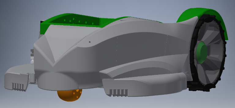
Back part (main part close to wheel) / hintere Teil (das große nahe am Rad) https://a360.co/2T7n6JD
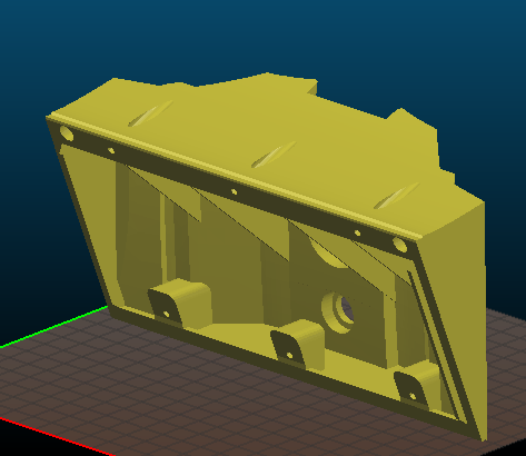
Motor Boxes, lower chassis part / Motorbox, untere Chassis teile https://a360.co/2EpFCTo
New front(nose), neue Front (Nase) https://a360.co/2IH0jj2
PCB lid (Camera) PCB Deckel (Kamera) https://a360.co/2TlbIJ9
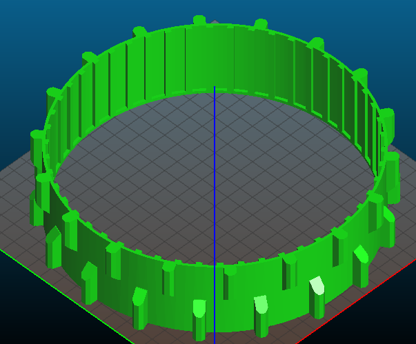
Blade protection / Messerschutz https://a360.co/2Ejde51
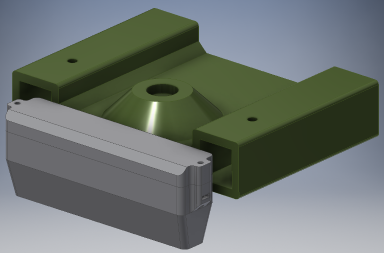
new PCB Box with large battery box / neue Platinenbox mit großem Batteriefach https://a360.co/2EpFTWq
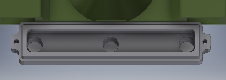
Silicone damper (mold) / Silikondämpfer (Formen) https://a360.co/2Tc8GYM
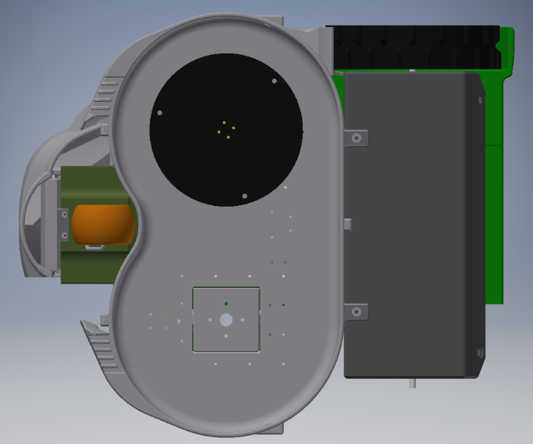
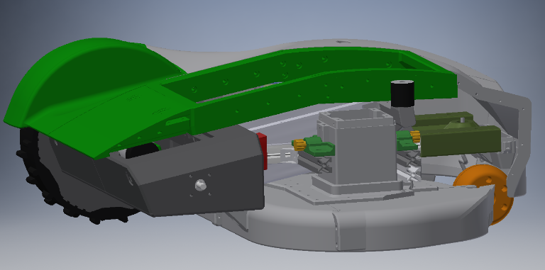
Ich glaube, ihr solltet die Dateien lieber herunter laden, in der Online Vorschau sind viele Körper ausgeblendet. Ich habe mein Arbeiten immer wieder Kopien von dem Original gemacht, so sind leider viele Dateien entstanden, die immer nur einen Teil der Arbeit enthalten.

It seems to be best to download the files instead of preview them online. Online seems to be some parts missing. I used lot of copies of origin project and changed only a few things in each. This results in lot of files which always contain just a few modified parts.But I used comments for documentation.
 
This is my current work. I build a new perimeter receiver box, new front bracket and on top of front bracket, hall sensor will be placed. I will share as soon as it is ready and work.
Front bracket seems to be a good place for hall sensor because it is easier to attach than no PCB box.
 
Neues Teil: Bedienpanel mit Not-Aus. Mich hat die ganze Zeit gestört, dass der Not-Aus keinen Platz im Design hat. Dies habe ich nun gelöst. Auf dem Heck wird das bisherige Cover (mit dem Ardumower Schriftzug) durch dieses Teil ersetzt. Das Design ist eine Fortführung des PCB Cover und hat eine leichte Spoiler Form. Daran kann der Not-Aus aus dem Shop und ein Power Taster (12mm Bohrung) befestigt werden.

New Part: Kill switch panel. I wanted to add a kill-switch. So I designed a new cover/panel for back section of chassis. It continues the design of PCB lid and looks a bit like a sports car spoiler. You can attach kill-switch sold in Ardumower shop and a power switch with 12mm bore diameter

Ausrichtung auf Druckbett / Orientation on print surface
kill.png


Kein Support notwendig / no support needed

IMG_0015.JPG

IMG_0016.JPG

IMG_0017.JPG

Attachment: https://forum.ardumower.de/data/media/kunena/attachments/2946/IMG_0017.JPG/
 
Zuletzt bearbeitet von einem Moderator:
Oben