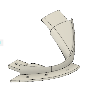
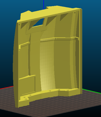
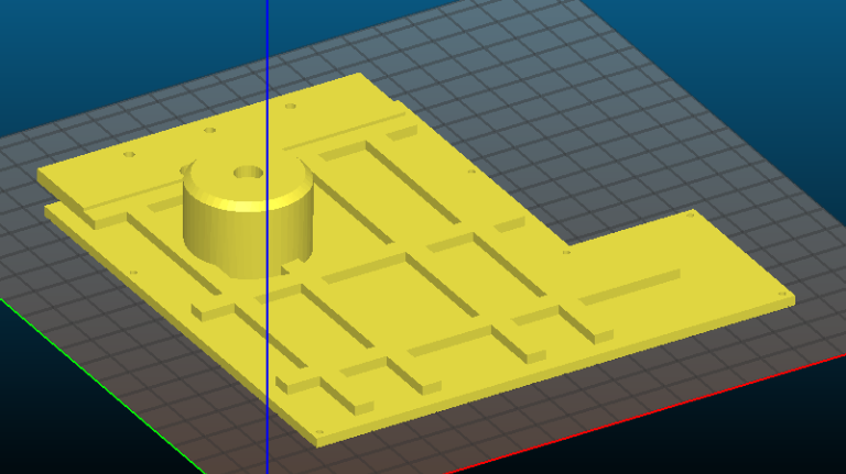
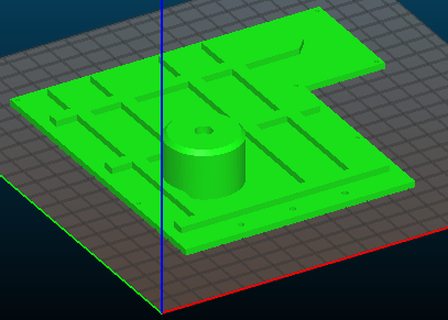
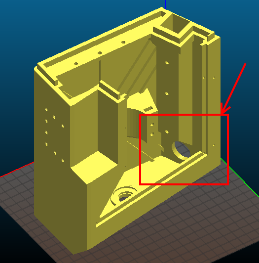
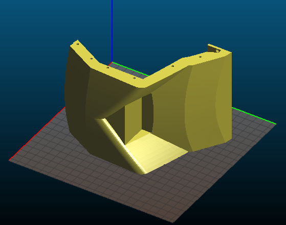
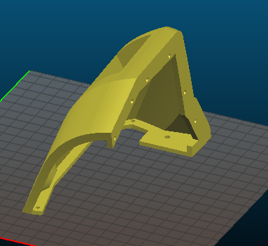
Mittelteil Chassis hinten, über Motoren: Das Mittelteil besteht aus zwei Teilen. Das untere Teil dient zum Verbinden der Radhäuser und als Aufnahmepunkt für die hinteren Dämpfer. Ich habe die Aussparung an der Unterseite beibehalten aber etwas verkleinert. Die Idee ist, hier die evtl. notwendigen Kabel rein zu ziehen und mit einem Deckel abzuschließen. Die Seitenteile der Radhäuser werden mit diesem Teil verschraubt.
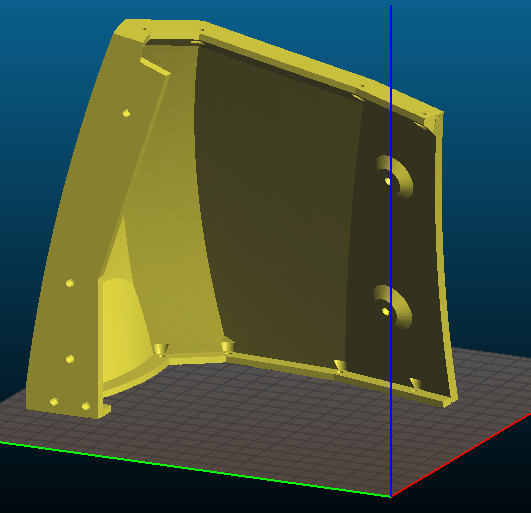
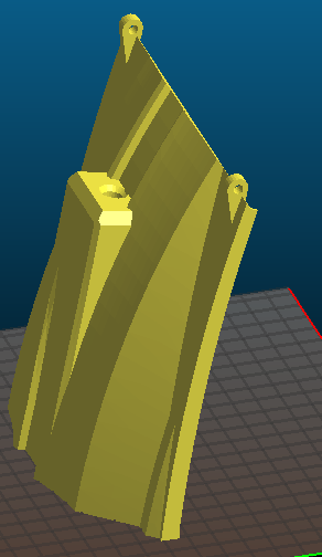
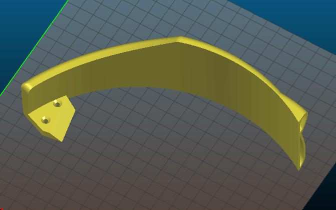
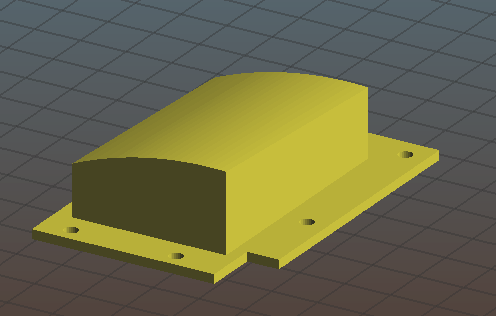
Für den Deckel wird es sicherlich viele Varianten geben, je nach persönlichem Geschmack. Ich habe einen Basisdeckel entworfen, der keine weitere Funktion aufnimmt. Wer möchte, kann den Deckel anpassen und Aussparungen für Displays, Buttons, Schalter, LIDAR Turm oder was auch immer dran basteln.
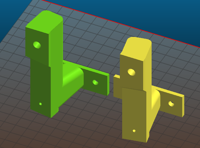
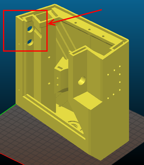
Beide Teile sind von mir nicht geprüft worden. Bei mir wird der Deckel einen Button und den Not-Aus tragen. Diese Version ist aber nicht fertig und kommt irgendwann später. Die Basis habe ich so auch noch nicht getestet. Da bei mir das Chassis beweglich als Bumper gelagert werden soll, plane ich den umlaufenden Rahmen an der PCB Box durch Alu Leisten zu ersetzen um Platz für die Bewegung zu erhalten (~+/- 2cm). Somit entfällt bei mir die Verbindungslasche für den Rahmen.
Ich stelle die Dateien aber dennoch hier rein, damit ihr euer Chassis vervollständigen könnt.
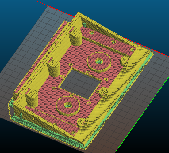
UPDATE: die Basis hat nun Schlitze für M3 Muttern, um den Deckel zu verschrauben
Middle section part on back of chassis, on top of motors: I split this part into two parts. The lower one connects the wheelhouses and also the upper chassis with the dampers on back side. There is a smaller cut-out on the lower side. If you need cables on this part (Buttons, Displays etc.) put them through this cut-out and close it with a small lid.
Also there is a lid/cover, which closes the box. In my opinion, there will be lots of different versions of this cover depending on your needs. Someone will put a Display here, buttons, kill switch, LIDAR tower or what else. Therefore, I only created a very basic versions without any holes and cutouts. It just closes the box and might be the basis for your development.
Please note, both parts are untested right now. I'm not going to print them because I plan a moving body. In my idea, the chassis acts like a bumper and can be moved approx +/-2cm in all directions. Because of this, I will not use the frame parts around the PCB Box as I replace them by aluminium bars. They will give some strength to the body but will need less space. Therefore, I need the lower part described here without the connection part to the frame. So I will not print it this way.
Also I will create a lid/cover which holds kill switch and a button. But this will come later.
I just provide the files so you're able to complete your print.
UPDATE: Basis part has changed so there are slots for M3 nuts to screw the lid to the basis
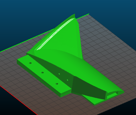
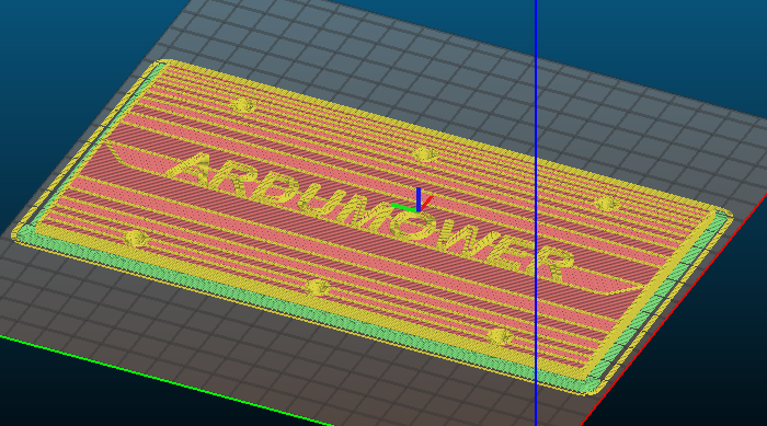
Ausrichtung auf dem Druckbett / Orientation on print surface
Support erforderlich / support is mandatory
Deckel um 22° drehen / rotate the cover in an angle of 22 degrees
Attachment:
https://forum.ardumower.de/data/media/kunena/attachments/2946/Chassis-lower-back-motor.png/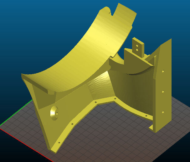
")