Arudmower auf Basis Denna L600 Neuaufbau

Hallo zusammen,

ich habe mich entschlossen diesem Projekt hier zu folgen und mir einen Ardumower zu bauen.
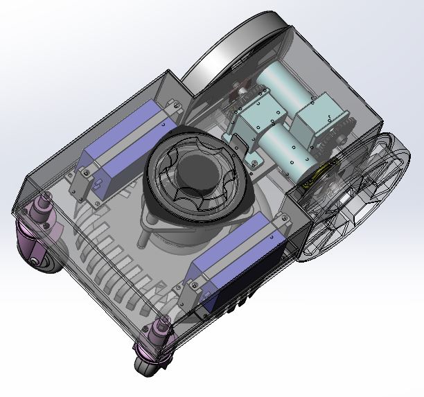
Ausgangs Mäher ist für mich ein Denna L600, diesen habe ich günstig erstanden aber defekt. Ich habe bereits die Teile für mich ausgebaut die ich weiter verwenden werde und im CAD modelliert.
Dies sind die Antriebsmotoren, Achsen und Räder, die Front-Räder, das komplette Mähwerk, sowie die Akkus.
Der Rest wird neu. Warum? Weil meine Rasenfläche sehr lang und Schmal ist aber dafür lang. Da kann ich keinen Grossen Globigen Mäher laufen lassen.
Weiter sollte das Mähwerk mit der Mäherbreite übereinstimmen damit bis zum Rand gemäht wird.
In der Beschreibung habe ich gelesen das eine Navigation anhand einer Karte für den Ardumower in Entwicklung ist, wie weit diese Entwicklung derzeit fortgeschritten ist habe ich leider nirgends lesen können.
Vielleicht weiß das ja jemand hier.

Aber nun mal ein paar Bilder für den ersten Eindruck.
Ardumower_Forum_2018-12-21.JPG

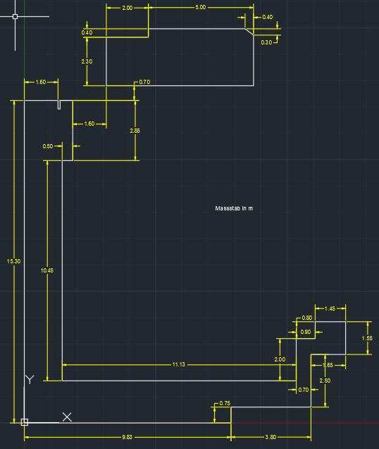
Das ist meine Rasenfläche, es ist auf Zwei ebenen die durch eine Rampe verbunden werden.
Ich weiss es sieht nicht einfach aus. B)

Mher_1.JPG

Das Gehäuse ist geplant aus 3mm Alu platten zu machen, oder ist das nicht empfehlenswert?

Mher_2.JPG

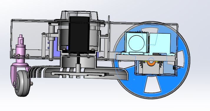
Das ist er im Schnitt.
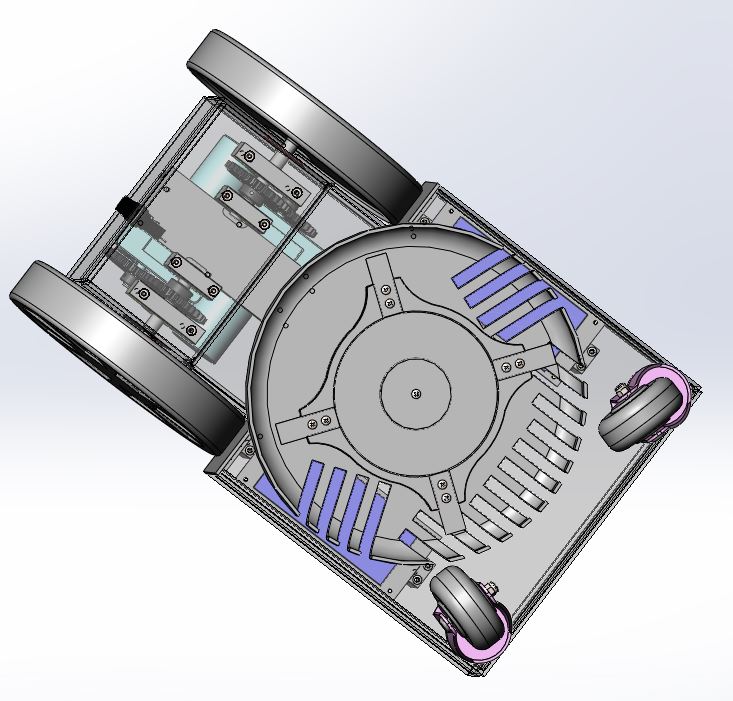
Mher_3.JPG

Und von unten.

Grüsse Marc
 
Hallo Marc,
ein interessantes Projekt.
Keine Ahnung wie laut der Denna L600 ist aber in einem Alugehäuse wird es sicherlich nicht leiser.
Bei mir laufen die hier im Shop erhältlichen Getriebemotoren. Inzwischen stört mich das Geräusch und ich werde beim nächsten Mower ein Kunstoffgehäuse aus CFK /GFK versuchen.
Was würde dein Mower mit dem Alu und den zwei Akkus wiegen?
Sind die Getriebmotore im Original auch Seitenversetzt angeordnet?

Gruß UWE
 
Hi Uwe

Nein im Denna sind die Getriebemotoren in einer Linie angeordnet. Da ich von der Breite ziemlich geschrumpft bin ging das nicht mehr... daher sind diese versetzt aber die Räder sind in einer Achse also sollte das kein Problem sein.
Aber ein guter Einwand mit dem Geräuschpegel. Ich werde die Motoren mal auf ner Aluplatte testen und eine Gummimatte zwischen bauen zum dämpfen.
Alu liegt bei mir nahe da ich ne Portal cnc Fräse im Keller habe und das dann Biegen und schweißen kann auf der abkantbank :)

Was ich eher dachte wegen der Elektronik und der Abschirmung durch das Alu, das es da Probleme gibt...

Gruß Marc
 
Abschirmung ist doch gut!
Dein Schleifenempfänger wird es dir danken.
Wenn Du dich hier durch das Forum kämpfst, wirst Du sehen das der Schwachpunkt, des hier zum Set gehörenden Schleifenempfänger, die Störstrahlung der Elektronik ist.
Insofern...........
Mein neuer Mower sollte auch aus den gleichen Gründen wie bei dir schmäler werden. Geht aber nur mit ungleich langen Radstand.
Ich bin gespannt wie es bei dir läuft.

UWE
 
Hi

Na das ist ja mal interessant ich dachte es hatte nachteilige folgen. Aber wenn das so ist dann werde ich den Weg weiter verfolgen.

Sag mal die Motoren von dem denna haben hinten noch Hall Sensoren drauf, irgend wie bin ich nicht schlau geworden aber sehe ich das richtig das das 1.3 Board diese Sensoren nicht braucht?
Oder gibt es ne Möglichkeit die einzigebinden? Wäre vielleicht nicht schlecht für die Positionierung oder?

Gruß Marc
 
Hi.
The Denna L600 motor have odmetry and you can directly connect them to the PCB1.3.
I use this platform for 2 years now without any issue.
The more complex is to cut a little the PCB 1.3 to put it inside the Denna chassis but if you build a new chassis it's not a problem.

The motor are very silencious for me

For the straight area the Bylane mowing, starting position and maybe RFID (in DEV actualy) can easily solve the issue by mowing parallel to the wire.

It's DENNA Platform.
https://www.youtube.com/watch?v=F2UFJ1DNCJk https://www.youtube.com/watch?v=s9w-ZZbiVvc https://www.youtube.com/watch?v=uRVwDlntp2o https://www.youtube.com/watch?v=2HWGd7ELcBg
https://www.youtube.com/watch?v=tc9ujlQuros
 
Hi.
It's 1440
but if you use the PCB1.3 : The diviser (need to solder /2 on back) so if you use AZURIT you need to put 720
By.
 
Hi Bernhard

Thanks for the encouraging videos. And the good news for the Sensor Connection.

I have a further question
What exacly you mean with the RFID (in DEV actualy)
How Schal that work.
Sorry that I‘m more a mechanical guy as an electrician ;)

Thanks Marc
 
The rfid in use with a Raspberry PI on the mower for a localisation of the mower at +-5CM on the wire.
The goal is to use it by many way:

Fast return to station:
When the bat is low the mower try to find the wire and follow it until find the station.
But if you have a very long perimeter it's take time for Nothing and make track on the grass.
So the idea is to put small rfid tag on the perimeter (10 or 20 or more) and when the mower find a tag and read it ,it stop to track the wire , rotate to the correct direction and run over the are to find again the next tag or the station.
Starting point:
Using the By lane mowing starting position is very good to cut a big area into smallest one that you can mow one after the other. https://www.ardumower.de/index.php/...ll-odometry-mouvement-control?start=100#14260 On the video you can see a start at 25ML from station using Odometry.
The issue is that it's not perfectly accurate (sometime start at 20Ml and sometime at 30ml)
With the tag underground ,the mower always start to mow at the same location +-5CM (in the extrem angle of the area for example).

Leave Island:
If you have island on your perimeter (arround flower for example ) a tag is use to avoid the mower rotate no stop on it.


Mow on a second Perimeter area:
NOT WORKING ACTUALY
On a particular tag the mower can totaly leave area1:
When find a tag on perimeter area1 the mower rotate at (x degrees) stop to read the perimeter area1 signal , drive 8 meters and restart to read the perimeter signal on the area2.
So use many areas totaly different but only one charging station.

But i need to find a way to start and stop the sender on the the area2 and if possible use a sender on battery. ????
 
Hi

thanks for the explanation, specially the part with the "Second Perimeter Area" will be very interesting for me as I have two areas to mow.

You have a clou when the"second area will problay work?

Marc
 
Hi

I thougth you are englisch in case of your Language Sounds Perfect.B)

Ans how i mean an idea for the Time cheudule of the Second perimeter area. Do you habe an idea when that will work?

Marc
 
Ok.
To select the area. it's not a problem, Simply add a variable in the timer to select the mowing area so the mower run on the wire until find the associate tag,
But for me it's not a problem.

The main issue is to manage the communication between the 2 or 3 sender and the mower and check if i can read 2 or 3 différents sender code to avoid issue on smag reading.


As i tell you before this part is only in DEV on my code and Don't work at all for the moment.

Also i need to check that i can leave the RFID tag underground for a long time without destroy them.

After 6 month underround my first tag is dead so !!!!!!!
 
Hi.
For protocol i Don't understand exactly what you mean.
It's 125 KHZ module and i only read the tag number (Don't need to write on it).

Remember i use my own version of AZURIT with a full communication with RASPBERRY PI.
So the RFID reader is connected to the PI by USB .
I adapt the Phidget Python Library to my code and after lot of time it's finally work

For RFID i have tested many reader and Always have issue with a too small reading distance exept with a PHIDGET PN1023 reader.

Here a picture of the Shop module.
(i also test a PN532 with the same result)
20181224_100349.jpg

Tag is not waterproof and is OUT after 1 or 2 weeks.
The reading distance is less than 4 CM so can't work on the mower.

After i test this one from ebay.
20181224_100328.jpg

The RDM module can read at 7 CM
i connect it on one Serial port on PCB1.3 (The WIFI was free on my PCB1.3)
But the reading speed is very slow and the mower need to track the wire at a too low speed.
So i stop to work with this module


Finaly i have old Phidget module and surprise the reading distance is near 10 CM.
1023_1.jpg

So i use it and connect it on the Raspberry PI.
But again the tag is not waterproof , I try to put them in pocket with silicone
20181224_094456.jpg

And now wait to see if it's more durable.


Next Summer i hope i can test all the feature in real autonomous condition.

By.
Attachment: https://forum.ardumower.de/data/media/kunena/attachments/3545/20181224_100328.jpg/
 
Zuletzt bearbeitet von einem Moderator:
Hi

Thats are good informations.
Any how i do not understand too much of these things a friend of mine are expert Here I guess after the howlydays He Is back and we can discuss more intensive. He Is working on things like that by bussiness.
 
Hi
In the meanwile I habe other question, the pcb1.3 has a size of 27,2 x 10,6 but I Can not find informations for the Fixing holes of the Board. Do somebody have the Position of These Wohles for me so that in do construction for it.

Thanks
Marc
 
Oben