Du verwendest einen veralteten Browser. Es ist möglich, dass diese oder andere Websites nicht korrekt angezeigt werden.
Du solltest ein Upgrade durchführen oder einen alternativen Browser verwenden.
Du solltest ein Upgrade durchführen oder einen alternativen Browser verwenden.
New English translation of V1.4 assembly instructions
- Ersteller sustainablestew
- Erstellt am
randalosgood
New member
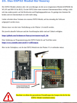
I am at step 25 regrading the supposed installation of the ESP32. It says "Wiring to the circuit board 1.4 must also be created from there.". WTF? How are we supposed to mount this module? I assume the diagram on the page refers to the wifi module we did not install(those seven pins) but are we supposed to just grab some wire and start soldering it however we please? This whole section has me thoroughly confused. Any help would be appreciated. Thank you.
You can solder it or you use the white plugs. It is helpful if you buy this set from Amazon: Crimpzange Dupont Stecker Set SN-28B Crimping Tool mit 2030pcs Dupont Steckverbinder und Crimp Pins Stiftleiste, 460 pcs JST-XH Stecker Kit + 5M 10pin Dupont Kabel, Crimpzange für 0,14-1 mm² : Amazon.de: Baumarkt


Thank you. Similar question about the White box plugs. I don't have enough to match the picture. But it does not say which ones I need to put in. Is there a way I should know what to do without asking here?

@W1976 Thank you for all your help. Can you show how the ESP32 is supposed to be mounted? I do not see a place in the board to put it. Should it just float around?I am at step 25 regrading the supposed installation of the ESP32. It says "Wiring to the circuit board 1.4 must also be created from there.". WTF? How are we supposed to mount this module? I assume the diagram on the page refers to the wifi module we did not install(those seven pins) but are we supposed to just grab some wire and start soldering it however we please? This whole section has me thoroughly confused. Any help would be appreciated. Thank you.
You are welcome. I think there are diffrent possibilitys. You can look on Thingiverse for a EPS32 cabinet. I have used a simple electronic caase like this from a building store. Abzweigdose IP54 75 mm x 37 mm x 40 mm 10 Stück kaufen bei OBI
Some questions:
1. Are there instructions how to install the GPS antenna on the top of the mower? My case has two small holes which look compatible with the antenna module, but I do not know where the wire goes.
2. Are there instructions how to install the rain sensor?
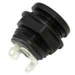
3. How do I wire the charging barrel plugs? There are three connection points. Which do I use?
Thank you
Mr. Tree
Active member
1. No and Yes
The 2 indication holes are for the antenna, make sure you dont install something close to it.
2. No
But there are hints and pictures were different people placed it. Its up to you.
For me, i placed it just in front of the Emergency Off with a printed casing. Below that i made hole of i think 8 mm for both wires. GPS and Rainsensor.
3. On the Boardsides are large positive and negative prepared connector holes, take those, doesnt matter which ones.
Make sure your wires/screws cannot touch the aluminium profiles. Best would be to solder a connector or wire to them.
Thank you for your time and answers. What I have are three connections, and I am not sure which two to use. Is there a diagram somewhere? I have had trouble searching for an answer.3. On the Boardsides are large positive and negative prepared connector holes, take those, doesnt matter which ones.
Make sure your wires/screws cannot touch the aluminium profiles. Best would be to solder a connector or wire to them.

ThanksHappy Birthday
English or German?
What do you want to do? Charging? Can you make pictures of your progress, is everything finished?
The voltage in the App?
English is preferred but google translate is functional, too.
When I hook up the battery and push the power button, the pcb beeps 2 times every couple seconds, the output reads "0.00V" in the console.
Code:
22:41:13.656 -> 0:0:38 ctlDur=0.02 op=0 freem=246959 sp=2000108C volt=0.00 chg=0.00 tg=0.00,0.00 x=0.00 y=0.00 delta=0.00 tow=268889000 lon=-137.41883885 lat=29.01550843 h=4999.0 n=0.00 e=0.00 d=0.00 sol=0 age=3.38
22:41:13.733 -> SWITCHING OFF (undervoltage)
..
..
[over and over]Ok that is good. I did not know if I could choose either outside pin or if one specifically had to be used.What do you mean, 3 connections? On the Plug? Just measure conductivity. Inside pin is +, outside PINS is minus.
I've uploaded some photos to this thread: https://forum.ardumower.de/threads/error-switching-off-undervoltage-bitte-helfen.24771/ if you wouldn't mind taking a look.
Thank you so much for your help!
I have made an attempt at translating the available German document for the V1.4 mainboard into English. Considering I don't speak German, I had to rely heavily on Google translate and then correct any awkward language by hand afterward. Hopefully the result is useful for other English speakers. Now I can actually start assembling my board....
Nice work on the manual! Came handy when doing my first PCB 1.4 . I recorded my assembly of the PCB 1.4 and made a playlist of 6 videos with English captions. If you feel like adding any links to the manual or anyone else to anywhere, please feel free to do so! I have added a link back to this thread on all of the video descriptions.
PCB 1.4 English assembly videos as I go, translations welcome
I did video series on PCB 1.3 and now making one for PCB 1.4 . Have so far soldered enough for 3 videos and planning to complete the whole board in next weeks or days. All translations, for any languages would be appreciated! I will add them to the videos...
forum.ardumower.de
shane smith
New member
Can anyone get a reply from info@marotronics.de even after paying for main board no reply?
My mistake emails where going to spam
My mistake emails where going to spam
Zuletzt bearbeitet:
Hi shane smith, I did not understand you. You have bought a mainboard, but did not get any information from Marotronics?Can anyone get a reply from info@marotronics.de even after paying for main board no reply?
My mistake emails where going to spam
shane smith
New member
I got some emails to say that I have made the purchase. That has been a few days ago. Nothing to say it has been shipped or when I might receive it.
Ok, now all clear. I will write to the Ardumower Team by Skype, I hope you get very soon a answer. Can you tell me your purchase order number, please? I can speak with Markus from Marotronics, but I need the purchase order number.I got some emails to say that I have made the purchase. That has been a few days ago. Nothing to say it has been shipped or when I might receive it.
Zuletzt bearbeitet:
