...wait for GPS Position Data

I don't understand .
For you the Q29 on my board is damage ?..
And you can't make your 6M module work wiithout modification on the PCB ?
 
Hi Bernard,
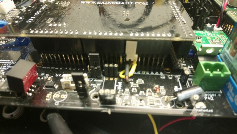
Following your pictures you connected GPS TX line to pin 4 of socket P5. The schematic shows pin 4 routed to emitter of Q29. With a working transistor the signal has no chance to pass the transistor. Per mistake the Due receiver pin is connected to the base of this transistor...only a shortage between emitter and base lets pass your GPS signal line to the receiver pin of DUE.

That's my electronic understanding...

Michael
 
OK.
Mistery of electronics !!!
Main is that it's work.
I have other board so when i have time i try it to see .
By
 
I mesured the same values like micserver. The conductor track TX3 and RX3 are reversed. So you have to connect them correctly.
My solution: I bend the pins comming out ot the board, soldered a wire on it and connected the wire to a pin strip like this: https://www.elv.de/econ-connect-stiftleiste-psl2g-1x-2-polig-gerade-rm-2-54-mm.html
DSC_0902.JPG

DSC_0892.JPG

DSC_0896.JPG

DSC_0898.JPG

DSC_0899.JPG

Attachment: https://forum.ardumower.de/data/media/kunena/attachments/2936/DSC_0902.JPG/
 
Zuletzt bearbeitet von einem Moderator:
:oops: in der Tat, da stimmen die Signalwege nicht. Leider haben wir das beim Testen nicht bemerkt.
Wir werden damit leben müssen, bis eine neue Überarbeitete Auflage kommt.
Bis dahin muss man sich behelfen, meine Lösung ist recht simpel.
Man muss nur Vorsichtig ran gehen dann gehts.
Die betroffenen Kontakte in der Mitte der Stapelleiste trennen und leicht biegen.
Bis Sie aneinander vorbei über kreuz laufen. siehe Bilder
Ein dickes Danke an alle die den Fehler zu Tage gefördert haben.
Attachment: https://forum.ardumower.de/data/media/kunena/attachments/191/20181011_211147.jpg/
 
Zuletzt bearbeitet von einem Moderator:
Oben