...wait for GPS Position Data

micserver

Member
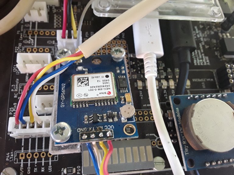
Hallo, habe heute das GPS Modul aus dem Shop angeschlossen ...blaue Leuchtdiode des Moduls blinkt rhytmisch im Sekundentakt ...aber es werden keinerlei Positionsdaten generiert. Im seriellen Monitor sieht zeiggt sich nur "999999999"...
Jemand eine Idee was ich du noch tun kann?

Gruss Michael
 
....bin etwas weiter: das Signal vom GPS Empfänger liegt mit einem Hub von 3.3V an der Basis von Q28, am Kolektor liegt IOREF mit 3.3V an...am Emitter, und damit an GPS_RX sehe ich kein Signal... ???
 
...noch etwas weiter: wenn ich während der Messung nur den Due boote liegt das GPS Signal am PIN 14 GpsRx des Due an, nach dem booten misst man stabile 3,3V, der Due zieht also das Signal auf Plus.
Hat jemand eine Idee woran es liegt?
..und in Englisch:
Trying to Read GPS Signal fails. Scope measurement shows the correct signal at base of transistor Q28, collector is correct connected to IOREF 3.3V but signal at pin 14 of Due board shows stable high 3,3V. The moment I reset Due board the correct signal can be measured at pin 14, after reboot signal is pulled to high again.
Any idea what's wrong?
Michael
 
Ich frage mich gerade hat das jemand schon mal getestet.
In der schematic geht das Signal GPS_RX auf den TX3 Anschluß vom DUE/MEGA. Das müsste eigentlich auf den RX3 Anschuss gehen. Kannst du das mal verifizieren? Einfach mal mit dem Ohmmeter durchmessen.
 
Ja, das Design ist genau so wie im Scematic gezeichnet. Wenn man denn Due bootet (also die Konfiguration seiner I/O's zurücksetzt kann man das Signal mit dem Scope am Pin (14 ist es glaub ich) sehen. Sobald der Due hochgefahren ist wird das Signal auf High gezogen...

Hat denn keiner auf dem 1.3er Board GPS laufen?

Gruß Michael
 
Ich vermute mal nicht, da die Hardware falsch gelötet ist. Gut das es dir aufgefallen ist. Ich entwickle gerade GPS für Raindancer. Da wäre ich dann auch auf den
Fehler gestoßen.
 
Hatte vor heut Abend das Board auszubauen und zu prüfen... nicht das doch irgendein Lötspritzer da irgendetwas verbindet...
Halt mich bitte auch mit deinen Erkenntnissen auf der Laufenden
Gruss Michael
 
micserver schrieb:
Halt mich bitte auch mit deinen Erkenntnissen auf der Laufenden
Gruss Michael

Ja, bitte.
Habe mein GPS dran, bekomme es aber ebenfalls nicht zu laufen.

Gruß UWE
 
Zuletzt bearbeitet von einem Moderator:
Wenn deine Messung stimmt, sind rx und tx am due vertauscht. Da hilft dann rx, tx direkt vom Stecker an die due Pins auf der Rückseite des PC zu löten. Dazu müssen dann die beiden Transistoren und die Emitterwiderstände entfernt werden oder die Leiterbahnen am due unterbrochen werden.
 
Bernhard hat das getestet mit dem PCB1.3 mit dem angehängten Code. Vielleicht geht es dann ja bei euch auch. Aktuell etwas merkwürdig.
Das verstehe ich vor allem nicht. Der Ausgang von dem GPS Modul geht an den Transistor Q28, welcher das Signal GPS_RX liefert. Und dieses geht an den TX3 Ausgang des DUE. D.h. hier ist Augang an Ausgang geschaltet. Das kann eigentlich nicht gehen, außer ich übersehe da was.
Man muss das ja eigentlich nur mit dem WLAN/BT Modul vergleichen. Hier ist es genau richtig am DUE angeschlossen.
Attachment: https://forum.ardumower.de/data/media/kunena/attachments/2936/GPSTest2.zip/
 
Zuletzt bearbeitet von einem Moderator:
Hi.
I use a M8N , Normaly it's the same as M6 .
No particular issue with PCB1.3 and my old azurit version or test soft from Roland.
All is 3.3V selected and if don't work simply reverse the RX and TX.

Don't forget the 2 jumpers on 3.3V
20180724_190107_2018-07-24-3.jpg

Attachment: https://forum.ardumower.de/data/media/kunena/attachments/3545/20180724_190107_2018-07-24-3.jpg/
 
Zuletzt bearbeitet von einem Moderator:
Ok, gelöst! Zur Info: Ich verwende die Orginalteile aus dem Shop, also auch den vorgeschlagenen GPS Empfänger.
Die Pfade sind wirklich verdreht, der TX vom GPS ist auf den TX vom Due geroutet. Habe an den langen Sockelpins die Beinchen für PIN 13 und PIN 14 durchgetrennt und über Kreuz verbunden ....Voila, es funktioniert!
Bilder folgen.

Ok,problem solved! Only for information: I use the original shop parts and the recommended GPS receiver.
Routing from GPS to Due is twisted, TX from GPS meets TX of Due. I gutted the long socket Pins 13 and 14 to Due and connected them crossed ... voila it works!
Pictures will follows.

Gruss Michael
 
Hi Michael.
Strange that you can't make it work.
I have tested the PCB1.3 with BN880 , M6 from marotronics and UBLOX M8N from EBAY and all of then send the data
The 2 M8N are faster to start sending data.
20180725_171519.jpg


With the 6M for marotronics it's OK with me without any change on the PCB1.3
Simply connect the RX to TX and TX to RX AND WAIT AT LEAST 5 MINUTES TO HAVE A FIXED .


Don't know for Q28 and Q29 but the main is that it's work.
Maybe you not wait enought and if you are Inside your house ,Are you sure the GPS receive sat ?
By
Attachment: https://forum.ardumower.de/data/media/kunena/attachments/3545/20180725_171519.jpg/
 
Zuletzt bearbeitet von einem Moderator:
Hi Bernard,
:) yes, I receive SAT, it works fine now.
The attached pictures show the signal path from GPS Module Transmitter (yellow cable in my mower) to the pin 3 of P5 marked with TX. The attached schematic picture shows the path from pin 3 via Q28 to Due pin RX 3....and there is the failure: it is connected to pin 14 instead of pin 15 of Due. Changing this connection is the workaround.
By the way, my Jumper setting (signal to 3.3V and Module power to 5V) is as described in ardu wiki.

Following my understanding your path to pin 4 of P5 can only work with a defective transistor Q29 (shortage emitter to base) which leads by luck to the correct Due pin.

Michael
Attachment: https://forum.ardumower.de/data/media/kunena/attachments/3659/20180725_202224.jpg/
 
Zuletzt bearbeitet von einem Moderator:
Hi.
Certainly it's better to not change the PCB and use 3.3V on the 2 jumpers.
I think if you put 5V and 3.3V It's not OK if the issue on PCB exist.
By.
 
Hi Bernard,
module works in a power range from 3 up to 5V :

Artikelnummer: 1600
Model: GY-GPS6MV2
ceramic antenna
LED signal indicator lamp
Power supply: 3-5V

...means the circuit works in the same way using 3.3V or 5V... I tried both jumper settings for module supply ...same behaviour. Relevant is the signal level, for the DUE we need 3.3V. (Both of us choosed the correct jumper setting for signal level).

Michael
 
Info: Du hast im Schaltplan - Bild mit Kugelschreiber an P5 (GPS) versehentlich „HC-SR04“ (Ultraschallsensor) geschrieben.
 
Oh, sorry...meinte natürlich GPS. War gerade beim 3D Entwurf der Frontpartie mit den Halterungen für die Sonarsensoren :)
Gruss Michael
 
Oben