Please write here all ideas and suggestions.
I collect you together in the first post.
Please write precisely and briefly, if possible with pictures / drawings.
I have already made a list and can complete it
- battery boxes bigger ...a connected BMS (PCM-L07S12) should fit in the box Dimensions?
- three sonars sensors in the front with adjustable "view" angel ... to adjust the sense area Optional?
-In front an extra box (for example for R-PI, Cam modul, Lidar..etc)
- No position for emergency switch/kill switch
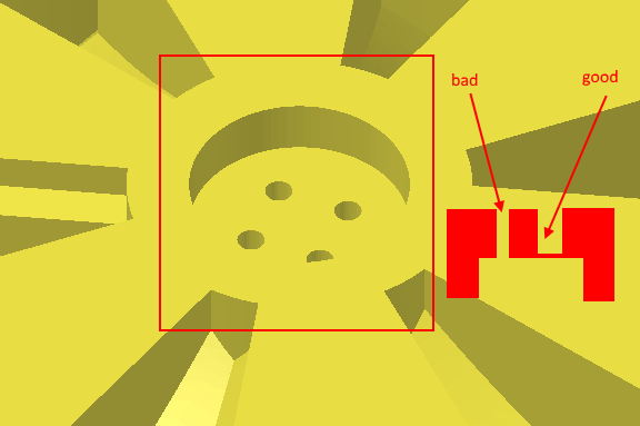
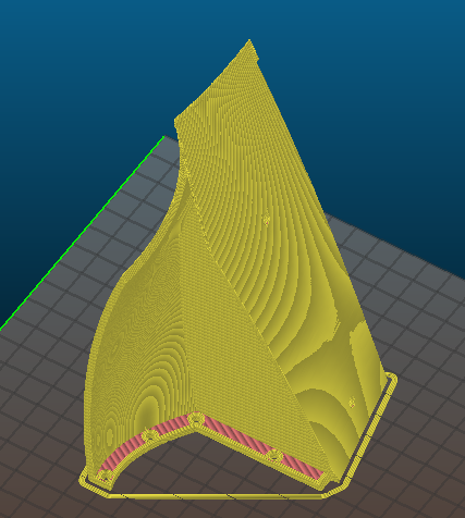
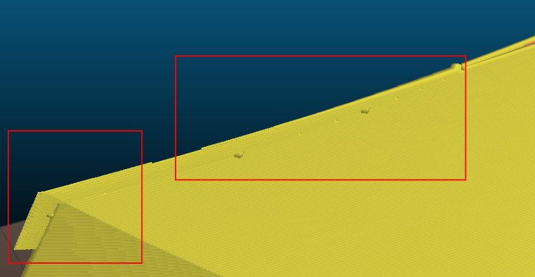
- On Thingiverse, there exist one mow motor mounting bracked which needs lots of support to print (Mower box holder left). There is an other one, which is better (Mower box holder right). Because they are symmetrically, it is better to print the right part twice.
- Bumper not clear (which kind of bumper, how to mount)
- option to use only one cutter motor with a greater cutting area ... 1 motor should reduce the power consumption ...
I collect you together in the first post.
Please write precisely and briefly, if possible with pictures / drawings.
I have already made a list and can complete it
- battery boxes bigger ...a connected BMS (PCM-L07S12) should fit in the box Dimensions?
- three sonars sensors in the front with adjustable "view" angel ... to adjust the sense area Optional?
-In front an extra box (for example for R-PI, Cam modul, Lidar..etc)
- No position for emergency switch/kill switch
- On Thingiverse, there exist one mow motor mounting bracked which needs lots of support to print (Mower box holder left). There is an other one, which is better (Mower box holder right). Because they are symmetrically, it is better to print the right part twice.
- Bumper not clear (which kind of bumper, how to mount)
- option to use only one cutter motor with a greater cutting area ... 1 motor should reduce the power consumption ...
")
