ROSMower, first attempt to build a lawn mower with ROS

Ich habe diese Treiber am 1.3 Board. Geht aber genauso mit dem 1.4. Board.

Mit der Adapterplatine V1.1 06/21 unverändert.

GND an GND
VR an Motor xxx PWM
Z/F an Motor xxx Dir
Signal an Motor xxx AVI (Hall)
EL an Motor Enable
5V nicht verbunden
Alles andere an K5 nicht verbunden.

Dann in der AmRobotDriver.cpp je nach Motor noch zwei Zeilen anpassen.


void AmMotorDriver::setBrushless(int pinDir, int pinPWM, int speed) {
//DEBUGLN(speed);
if (speed < 0) {
digitalWrite(pinDir, HIGH) ;
//if (speed >= -2) speed = -2;
pinMan.analogWrite(pinPWM, ((byte)abs(speed)));
} else {
digitalWrite(pinDir, LOW) ;
// if (speed <= 2) speed = 2;
pinMan.analogWrite(pinPWM, ((byte)abs(speed)));
}
}

Drehen die Motoren nicht an, dann die Zeilen auskommentieren. Drehen die Motoren im Stillstand dann Wert um 1 erhöhen.
Achtung:
Batterie an P+ und P-
Vor Anschluss an das 1.3 oder 1.4 Board sollten die Motoren mit einem 10k Poti an GND und 5 Volt und der Abgriff auf VR einwandfrei laufen und auch bei GND an ZF die Richtung umschalten.
 

Anhänge

  • 20211022_162010.mp4
    103,7 MB
Zuletzt bearbeitet:
Dem Mähmotor habe ich noch nicht angeschlossen. Der hat aber eine eingebaute Treiberplatine. Nur Gnd v+ Brack und Hall wird herausgeführt. Wird direkt an das Adapterbord angeschlossen.
 
Alles funktioniert mit der aktuellen sunary SW wie beschrieben einwandfrei. Schnell langsam rechts links. Keine Probleme. Das sind universelle Treiber mit denen ich schon lange arbeite. Funktionieren mit fast jedem Bl motor
 
An Hoverboard Motoren wäre ich auch interessiert. Die scheinen ja ziemlich leise zu sein. Was ist eigentlich der Nachteil gegenüber den aktuellen Brushlessmotoren? Ich vermute mal das die Hoverboard Motoren aufgrund ihres Durchmessers auch einen guten Drehmoment haben. Hersteller Kress und Navimow nutzen die doch auch.
 
Hoverboard Motoren sind ja nichts anderes als brushless Motoren und somit sind diese entsprechend leise. Drehmoment haben die ohne Ende, die sind schließlich dafür konzipiert, 150kg Mensch mit bis zu 20 km/h zu fahren. Für einen Rasenmäher sind die eigentlich überdimensioniert und viel zu schnell. Laufen aber auch langsam erstaunlich ruhig.
Da es Radnabenmotoren sind, sind diese extrem kompakt und super einfach zu montieren. Da braucht man keine Sorge zu haben, wie man den Motor + Getriebe in dem Gehäuse unterbringt oder wie man das Rad befestigt bekommt. Das Rad ist fix montiert und Getriebe gibt es auch keines, folglich auch kein rasseln vom Getriebe. Außerdem sind die extrem günstig im Gebrauchtmarkt. Da gibt es komplette Hoverboards für 20€ als defekt. Meist ist der Akku hin oder das GEhäuse gebrochen. Beides nicht relevant, wenn man Roboter draus baut. Konzipiert sind die für 36V, laufen aber auch mit 24V problemlos.

Wo Licht, da auch Schatten. Aktuell sehe ich folgende Nachteile, die es zu bedenken gibt:
- schwer (nicht gewogen, aber sicher 1,5kg pro Motor)
- Reifen ohne besonderes Profil, eher glatt. Könnte bei Steigungen zu Problemen führen. Es gibt aber welche mit "Cross" Bereifung und der Reifen kann auch getauscht werden
- wenige Odometrie Ticks. Ich erhalte 90 Ticks pro Umdrehung. Für ein Hoverboard bei 20 km/h mehr als genug. Für einen langsamen Rasenmäher möglicherweise nicht ideal
- Hoverboard PCB recht groß, je nach Chassis schwierig unterzubringen
- Hoverboard PCB hat Ladeschnittstelle implementiert und erkennt dies. Eine aktive Abschaltung der Ladung scheint aber nicht gegeben zu sein. Wenn man nun zusätzliche Verbraucher dran hat, dürfte eine verlässliche Abschaltung scheitern. Somit werde ich zumindest die Lade- und Batterieschaltung vom Ardumower entsprechend nachbauen

Als Motortreiber nutze ich die Platine des Hoverboards. Das ist ja schließlich nichts anderes als ein dual Motor Treiber für genau diese brushless Motoren. Die gehackte Firmware ist wirklich gelungen und bietet viele Arten, die Motoren zu steuern. Von UART über PWM bis Analog ist alles möglich und implementiert. Aktives Bremsen oder Coasting, Stromüberwachung, Temperatur des Treibers, Überwachung der Batteriespannung-> alles schon vorhanden.

Warum ich diese nicht mit den BLDC Treiber vom Ardumower Projekt betreibe?
- Kosten von 2 Treibern höher als vom gesamten Hoverboard aus dem Gebrauchtmarkt
- ich habe keine Parameter gefunden, mit denen die Motoren zufriedenstellend laufen
- Gewissheit, dass Hoverboard PCB in der Lage ist, die Motoren zu speisen (Stromstärke, Bremsen usw.)
- die extrem simple Integration des Hoverboard PCB als Motortreiber

Für mich hat besonders der Preis für zwei Motoren mit Treibern überzeugt. Für 20€ bekommt man das nirgendwo sonst. Zudem baue ich gern was eigenes und beschreite (für mich) neue Wege. Es ist für mich in erster Linie ein Hobby. Wenn ich nur Rasen gemäht haben will, kaufe ich für einen Bruchteil der Ardumower Kosten einen kommerziellen beim nächsten Baumarkt.
 
Ich denke mal wenn Segway mit dem Navimow das mit Hoverboard Motoren hinbekommt, müsste das auch für den Ardumower möglich sein.
 
Danke Paddy für deinen Beitrag, muss mal schauen ob ich mir ein gebrauchtes Hoverboard für einen kleinen Preis finde.
 
Danke Paddy für deinen Beitrag, muss mal schauen ob ich mir ein gebrauchtes Hoverboard für einen kleinen Preis finde.

you need to take care on 2 point :

The correct (with all feature) firmware on the net is build for only one kind of main board with STM32F103RCT6

the 2 other firmware are not so advance.

Hoverboardhack for AT32F403RCT6 based mainboards​

Hoverboardhack for split mainboards​


VERY IMPORTANT AND NEVER SEE ON THE NET : Before solder the 4 pin for ST Link programmer you need to empty all the big capacitor locate on the PCB (using the hoverboard LED for example).
 
Milestone reached.
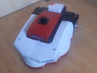
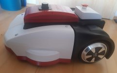
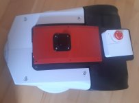
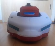
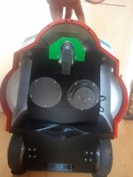
HoverMower (name of 3D printed chassis) is complete now. Everything fits perfectly and is operational. You can equip it with any electronics you want, a PCB1.3 should also fit inside the PCB Box (red). As already explained, you can use a simple UART interface to control each motor. You'll get odometry data, current sense and others back. I tried to re-use as much as possible from Hoverboard. So I took motors, PCB, battery, chargercharger plug, button and even LED headlights.

ROSMower is a HoverMower operated with ROS, robot operating system It is also prepared for more interesting tasks now. Equipped with NVidia Jetson, LD06 Lidar, Intel Realsense D435 stereo depth camera, BNO085 IMU, lawn might be out of chances. For power monitoring (battery, charge, disconnect battery), control mow motor and to sense perimeter wire, a base controller (Arduino Nano) has been implemented.

Right now, ROSMower can be driven around by a PS4 bluetooth controller (teleop). Next step will be implementing RtabMap for mapping and localization.

As this project becomes even more complex, I've created a new Git organization named HoverMower (https://github.com/HoverMower). It contains repos for documentation, 3D filed (STL and STEP), base controller firmware, related ROS packages and so on. It is up to you to cherry-pick what ever you need.

Documentation can be found here (lots of documentation still missing) https://hovermower.github.io/
 

Anhänge

  • 20220128_121141.jpg
    20220128_121141.jpg
    96,7 KB · Aufrufe: 33
  • 20220128_121148.jpg
    20220128_121148.jpg
    120,1 KB · Aufrufe: 22
  • 20220128_121151.jpg
    20220128_121151.jpg
    76,6 KB · Aufrufe: 22
  • 20220128_121208.jpg
    20220128_121208.jpg
    75 KB · Aufrufe: 33
  • 20220128_121225.jpg
    20220128_121225.jpg
    167,2 KB · Aufrufe: 35
Next Milestone reached. I had some hard times to get ROSMower up and running. It was easy to set up ROS to teleoperate the robot around. It was also easy to get Lidar and IMU working as well as my base controller, which acts for power management, perimeter and bumper.

But the Intel RealSense D435 stereo depth camera was really hard to get running. In general, they're easy to set up even with ROS but things become complicated with NVidia Jetson devices. A special combination between JetPack (OS Image for Jetson), Realsense Library, RealSense ROS wrapper and camera firmware did the trick.
In the end, it doesn't seems to be complicated but it was hard work to figure things out. If someone is interrested, see here https://hovermower.github.io/ROSMower_D435.html

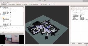
Next step was to get RTABMAP up and running. This software is used to create 3D mapsd on depth information of camera and lidar. I had to try different configurations until I got it working. I ran a short test through my house and got a 2D (still fighting with 3D) map of robots surrounding. It might be not that impressive to you but I'm really happy that I reached this goal

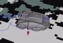
Also I had luck with creating a URDF model of robot which gets used for visualization and simulation.
 

Anhänge

  • image (1).png
    image (1).png
    88,9 KB · Aufrufe: 33
  • image.png
    image.png
    674 KB · Aufrufe: 34
How do you imagine to ensure the borders? Pure optical is a little bit risky because of the changing surrounding in a garden.
Will you use perimeter wires? Or do you have a lawn with barriers around?

I can imagine that you can get a very robust but flexible implementation if you combine optical mapping with RTK orientation. The mower could drive/orientate in the optical map area when RTK is lost. The mower can synchronize its orientation in the map when RTK is available.
But it would be hard work to implement all decisions in the software when to trust the optical map and when to trust the RTK orientation.
 
To be honest, I don't have concrete plan here and I'll see, how well it will work with camera only. However, for the beginning and safety purpuses, I'll use existing perimeter wire of Ardumower. I did some tests and it works reliable to stop the robot if both perimeter coils are out. This should never happen if ROS navigation stack and SLAM once works. But who knows ;-)

The RTK stuff is really interresting to me and I follow it regulary. However, it is an expensive path, I would need a base and rover and both charges up to 550€ min. I choosed Lidar and stereo camera not because they're cheap (they're not, you can get a RTK kit for the same) but I had some luck to get them for a really low price.

The entire build is some kind of R&D for me to learn ROS stuff. It might result not in an operational mower at all. Maybe I need to do it with planned randomness in worst case. The overall design principle I was following with the chassis was to get it independent from any electronics or firmware. So it will not be a big task, to get it running with common Azurit version.
But for me, it is not a waste of time as in my opinion, learning stuff is always important.

What I'm most fascinated about ROS is, you find a bunch of packages for SLAM, navigation, path planning, sensor fusion and nearly all of them are open source. As all packages uses some kind of common messages, you can swap them with ease (in most cases). As companies and universities uses ROS for differential drive robots (like mowers), robot arms, self-driving cars as well as autonomuous Mars rovers, it might be good enough to mow lawn as well :)
 
First test run of Hovermower on a sunny day.
Works good so far but still lot of work. First I need to get rid of poor wifi signal in garden. I have one router and two repeater acting in a mesh in my house.
But this seems not to be working well outside. Maybe I need some kind of wifi bridge to cover the garden. Any ideas?

LD06 works great outside even in bright sun. I use rtabmap_ros together with realsense stereo camera for slam. It works but consumes much ressources. Maybe I'll start with gmapping first and use the camera only to detect obstacles.

One major topic is coverage path planning and I hope to get this working as well.

For more details, have a look at the video description

 
For this test, I compare how different mapping packages influence the path coverage of a given area.
I tried to run all tests on the same area.

At first glance, it seems gmapping did the best job as it covered the area as fastest.
rtabmap did a really good job even if it tooked the most time. Expect from the beginning and the end, it runs most smooth. The lag at beginning might be caused move_base wasn't able to solve the path as it was too close to obstacle.

All tests show really time consuming oscillation when rotate. I didn't see this when I set a goal manually. However, this seems to be the main cause why path coverage didn't worked as expected. Until now, I don't know which causes this oscillation but it might be the following:
- rotate too fast result in lost of lidar position
- pid settings of Hoverboard motors
- goal tolerances of move_base are set too fine

 
Making only small progress. After I noticed the OpenMower project, a ROS based mower, I started to migrate my build to incorporate with their software as things like path coverage are done there. Also they have build some behavior trees, which I was missing so far.

But this meant, I had to purchase an Ardusimple Kit (two). I really tried without RTK-GPS but it is not feasable for me to solve localization with visual odometry only.
But even with RTK-GPS, things are not trivial at all. I use robot_localization package, which isn't used by OpenMower project as they build their odometry source different than it is commonly solved in ROS.

However, after several test, I was able to get it up and running. The root cause was IMU heading. If I use absolute orientation, things get worse. But by using only yaw velocity, I was able to localize correctly.

 
Making some progress. HoverMower now uses OpenMower ROS package for mowing. But I had to change some things, especially robot localization. I've written a node which translates ublox/navrelposned messages to nav_msgs/odometry. This gets fused with robot_localization package.

But still fighting with oscillation.

Mowing perimeter with slic3r_coverage_planner
 
Schon sehr interessant.
Frag mich wie auflösend die Aufnahmen sind. Bei dir ists mit der Wand rumherum sogesehen ideale Bedingung - ich hab zum Nachbarn Maschendraht. Ob der den erkennen könnte?
 
Oben