RFID On PCB1.3

bernard

Well-known member
Here a solution for RFID Tag reader.
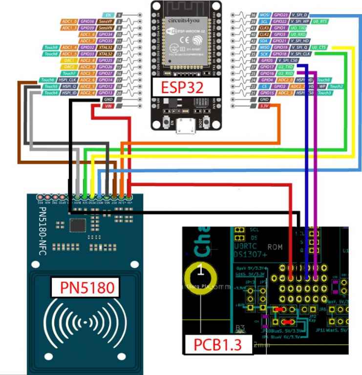
I have really test many reader and finally i use the PN5180 because (it's not 125KHZ and the reading distance is >10 CM with card)
Here the component used (sorry but unfortunatly only in china ????) replace the bbay with ebay:p https://www.bbay.fr/itm/10pcs-RFID-...e=STRK:MEBIDX:IT&_trksid=p2057872.m2749.l2648 https://www.bbay.fr/itm/PN5180-NFC-RF-I-Sensor-ISO15693-RFID-High-Frequency-IC-card-ICODE2-Read-Write/263259188762?hash=item3d4b786e1a:g:aZ8AAOSw7PZZ3yLq https://www.bbay.fr/itm/ESP32-ESP32...050295?hash=item3d3dd00df7:g:WiYAAOSwyrFZO5XR
Simply remove the HC05 Bt module from PCB1.3 and connect the ESP32 instead:
wiring.jpg


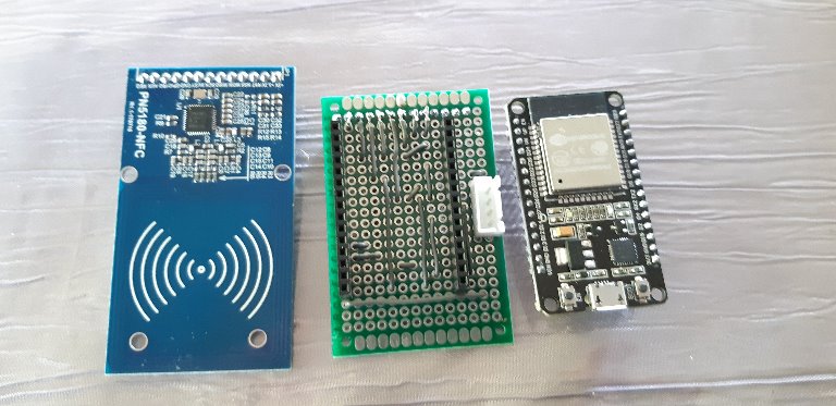
With a simple wired board:
20190530_081859.jpg


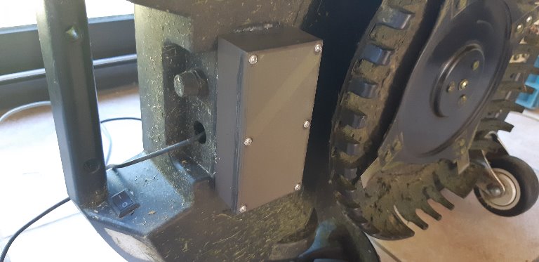
And inside the mower.

20190601_165431.jpg


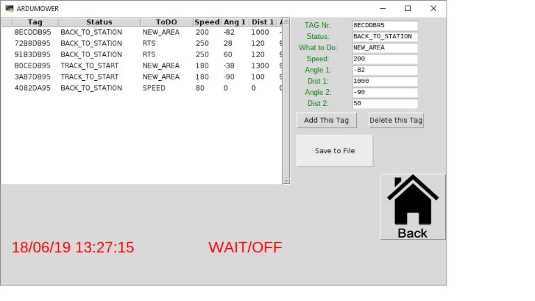
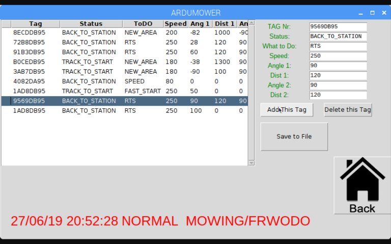
The ESP32 is now used by arduremote or Pfod and a new message is add with the tag ID find when the mower detect it.
The Azuritber send the tagID to raspberry PI and a database checking can tell the mower what to do.
Next step is to Do all the job in the DUE but it's difficult to enter the data in the DUE.
https://github.com/Boilevin/AzuritBer/tree/RFID/TEST FILE/ESP32_PFOD_PASSERELLE_OK
All work like a charm for the moment(With a PI3B+) :)
 
Wow, someone has been busy. Is all changes needed marked with 'RFID PARTS ADDED'`?

btw. can't see trough card with light, how big is chip/antenna inside. Just thinking if card can be cutted smaller
 
'RFID PARTS ADDED'
ESP32_PFOD_PASSERELLE_OK is the code you need to put into the ESP32 using arduino Ide .
And use PiArdumower and ardumower from the RFID branch.
The "fast start" (use tag to leave the wire and go faster on other part of the area when start with timer) is not finish but the fast return to station and second AREA works perfectly using timer.

Just thinking if card can be cutted smaller
At beginning i thought also that tag is better but no problem with the card.
To cut them I Don't know but i have 6 cards 2 or 3 cm under ground and no issue for the size .
In the picture the distance between ground and reader is near 6,7 cm and the reader read easily at more than 10 cm.
 
Cool solution, thanks for sharing.

You say RPI tells your mower what to do if you hit a given Tag ID. In my opinion, this is the best solution, I wouldn't add this to Firmware directly. Because you've already a RPI inside the mower, there is no benefit of moving this to DUE. It has lots of drawbacks because it is hard to manage here.

In my opinion, the current firmwares (all of them) do lot of stuff and it is not that easy to test new features. My plan for winter season is to move everything to ROS and to get the Firmware as small as possible. Firmware should only manage motors and stops when sensors triggers, ROS then need to plan the next movements. I think the winter season will be too short for this task :)
 
You say RPI tells your mower what to do if you hit a given Tag ID
Yes i have add a status in the firmware so when i find a tag i can search for (tag UID AND status) and if all match i put the mower into a new state using a PFOD command.
Here a screen copy of the setting and it's only this parts (and the search method) i need to build into AZURIT:huh:
RFID_PAGE.jpg


the current firmwares (all of them) do lot of stuff
Yes but actualy the mowing state have a loops/sec near 13000 so i can had some stuff.

it is not that easy to test new features
It's why i use the PI to record all the console data (i also add a lot of Console.print in the code) and it's really help a lot for debug.

Last year i have try to setup ROS in the PI but after a lot of work it did not work very well and very slowly.
The big issue is that at 0.5m/s the mower have only some millisecond to react (for example on bumper or on IMU driving) and i'm not sure ROS can react faster BUT Yes it's certainly a very good possibility.


Actually the Perimeter Range is not enough for me and i need to find a way to solve this and the 100% reliability because i want to mow near a lake(pond) because the mower don't like water :cheer: .
Attachment: https://forum.ardumower.de/data/media/kunena/attachments/3545/RFID_PAGE.jpg/
 
Zuletzt bearbeitet von einem Moderator:
Hello
I will try this solution for my island problem.
Actuall i start to order. Lets wait for the ship from china...
Do you printed the box for the reader and esp? Or is it a standard box?
Best regards,
Bjoern
 
Here the description of the Actual RFID setting into PyArdu
.
The setting screen
RFIDSETUP.jpg


TAG Nr : it is the unique UID of the card that you put under ground.
Status : use to select the action to do according to the mower actual status(same tag can be use to fast start or back to station 1AD8DB95 for example)
What To DO : when a card is find and mower status and rfid status match : it's what the mower do.
Speed : is the new setting speed (for example the back to station is possible at PWM=255)
Angle1 : is the rotate angle after find the tag.
Distance 1,Angle2,Distance 2 are only use to go into a new mowing area.
Distance 1 : is the distance that the mower drive before change to Angle2
Angle2 : is the second rotate angle after distance 1 driving
Distance 2 : is the distance that the mower drive before wait for the signal of the new area.


And here the video :

It's the Fast start to area2 using timer.
At 40 seconde, mower detect the tag 1AD8DB95
At 1 min 35 seconde, mower detect the tag B0CEDB95
At 2 min 30 seconde, mower detect the tag 8ECDB95 but ignore it because the mower status is TRACK_TO_START
https://www.youtube.com/watch?v=NGX7KlfbtKA&feature=youtu.be Attachment: https://forum.ardumower.de/data/media/kunena/attachments/3545/RFIDSETUP.jpg/
 
Zuletzt bearbeitet von einem Moderator:
@stockfisch
The box is 3D printed and contain only the rfid reader PN5180 (The ESP and PCB is locate Inside the mower.
Here the file:
 
Bernard schrieb:
@stockfisch
The box is 3D printed and contain only the rfid reader PN5180 (The ESP and PCB is locate Inside the mower.
Here the file:
My plan is place rfid reader and esp32 to bottom of motor box (inside) about 5-6 cm to ground. If it's not work then something else.
 
Zuletzt bearbeitet von einem Moderator:
Thank you!
I can print with 1% speed. The reader is on the long way from China...
Do i need the GY88 for the Rfid? I have one but actual it is switched of. I dont need it because i always mowe Random.
Best,
Bjoern
 
Do i need the GY88 for the Rfid? I have one but actual it is switched of. I dont need it because i always mowe Random.
YES and i Don't understand why you mow only in random ??
Also i never test the firmware without IMU (It's also the tilt safety)

Connect it (see jussip post for wiring)
Put arduremote in developer mode (into info)
Into setting bylane ,using arduremote adjust the yaw Opposite Roll dir right and left for the 3 lanes
it's realtime dir adjust using the slider , so it's very easy to do this until you have parallel (do not change the 3 fixed yaw)
Set the max lane lenght to 30 meters for example.
Now Into PFOD Setting MOW set the mow pattern duration to 60 minutes for example, by this way the mower change from by lane to random automaticly to avoid mark on the grass
Here the result
https://youtu.be/FiswnNuOPOM
 
Hi
Now i have nearly all components to start RFID.
Only the ESP is the wrong one. The new one will come next week.
Is there somewhere a kind of manual for installing the Raspberry?
Special the part to install the PiArdumower soft. Where i have to put what?
Thanks and best regards,
Bjoern
 
Oben