Husqvarna 260 ACX - RTK mod

@Reihtaug Sur le 265, tu peux aussi réutiliser le module ultrason. Je t’en dirai plus dans deux semaines, lorsque je serai de retour d’un déplacement professionnel. Le module US du 265 est un peu différent de celui du 260.
Le kit sera disponible dans la nouvelle boutique, qui ouvrira bientôt. Il y aura également plus d’informations sur le câblage.
En tout cas, c’est la bonne décision d’utiliser les nouveaux modules.
Il y a aussi de nouvelles possibilités d’utiliser SAPOS / NTRIP via WiFi sur le Pi.
Plus d’infos à ce sujet suivront bientôt.
(Thank's chatgpt for translation)
 
Der ACX 260 ist jetzt in vollem Betrieb und hat Alfred ersetzt. Trotzdem wird Alfred natürlich bleiben und hier und da auch noch zum Einsatz kommen. 😉
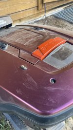
Ich habe dem Automower jetzt einen Regensensor verpasst - ganz im Alfred Stil.

IMG_1299.jpeg
IMG_1300.jpeg
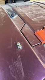
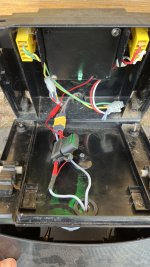
Dazu habe ich mir im Güde Ersatzteilshop zwei der Messköpfe vom Alfred gekauft und diese dann einfach mit einem Kabel am I/O Board angeschlossen - fertig! 👌🏻😬
Als Halterung habe ich mir eine angeschrägte Platte gedruckt, da das Gehäuse des Automowers an keiner passenden Stelle gerade ist. Dann habe ich zwei Löcher in die Haube gebohrt und die zwei Messköpfe dann mit Muttern von unten verschraubt. Als Abstand zwischen den Köpfen habe ich mich tatsächlich auch an den Abstand vom Original gehalten (edit: ich glaube, ich habe es etwas weiter gemacht als beim Original). Wem der Sensor zu früh auslöst, könnte ihn auch ggf. etwas vergrößern.

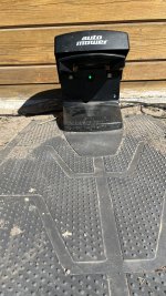
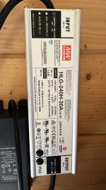
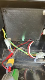
Außerdem habe ich das Dock fertiggestellt und mir eine Halteplatte für eine LED gedruckt und einen KFZ-Sicherungshalter in die +Leitung eingelötet. Die Stromversorgung der LED habe ich hinter der Sicherung angebracht, sodass es sofort sichtbar ist, sollte die Sicherung mal durchbrennen.
IMG_1311.jpg

IMG_1301.jpg

IMG_1308.jpg

Wer die Dateien benötigt - egal, ob es die .ino für die Steuerung aller Sensoren oder die .stl für den Regensensor oder Dock ist, kann sich gerne melden!
 

Anhänge

  • IMG_1310.jpg
    IMG_1310.jpg
    2,4 MB · Aufrufe: 2
Zuletzt bearbeitet:
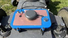
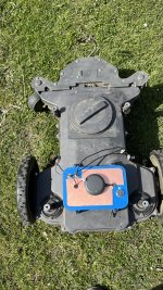
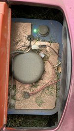
Ich habe nun noch meinen Deckel mit einer PCB-Rohplatte ausgestattet - nicht schön, aber es funktioniert! Damit habe ich teilweise bis zu 10 Satelliten mehr als vorher. Dadurch erhoffe ich mir einen stabileren fix in engen Passagen. Außerdem habe ich einen Kippschalter (250 VAC) eingebaut. Der 12VDC Schalter (bzw. dessen LED) ging nach mehreren Tagen nicht mehr - das war aber absehbar, da ich ihn ja mit 30 VDC betrieben habe. Nun habe ich den Schalter eingebaut und gleich mit einer Staubabdeckung, die ich mir damals schonmal als Ersatz für Alfred im Güde Ersatzteilshop bestellt hatte, darüber gezogen und oben drüber die gleiche grüne LED verbaut, wie ich sie im Dock habe. Die Staubansammlung auf dem Mäher ist wirklich enorm! Daher kann ich nur jedem raten, so eine Staubkappe zu nutzen! Ansonsten wird der Schalter nicht alt.
IMG_1387.jpg
IMG_1389.jpg
 
I had a Tallysman antenna laying around from an old project. But they are very expensive so I cannot recommend buying them instead of the ublox one. The receiption seems not to be better compared to the u-blox one on my Alfred.
 
@KadaverJoe : Je serais heureux si vous partagiez quelques informations avec moi. J'ai quelques questions. Surtout lorsqu’il s’agit de charger la batterie. Je ne comprends pas comment cela fonctionne sur cette plateforme. Pouvez-vous décrire le circuit en détail ?
Hello Reihtaug,

what would you like to know exactly? I am happy to help.
 
Hello KadaverJoe,

I haven't had my hands on the kit yet, so I still have a lot of questions ;)

If I understand correctly, the owlRobotics board doesn't measure current directly (unlike on the Ardumower).

So, do I need to add an INA260 board?

I also thought I saw a UBEC voltage regulator in the photos. What's its purpose?

Sincerely
 
Hello Reihtaug,

owlRobotics board measures the Voltage of the battery directly so you don't need a INA260 board. I bought a diode to seperate the battery from the charge power. Otherwise Sunray would be in "charge" state all the time. You will get a cable with a little 75K Ohm resistor soldered in it with the owl board. Thats for the charge recognition and will devide the incoming 30V down to max. 3V.
Also, the avg current of each single motor is measured by each driver and can be shown by Sunray as well. So you can define your max settings for mow and gear motors and it will show the drawn current in the app.

The UBEC is only neccessary if you want to use a RPi 4 instead of a Pi 5. The Pi 5 does not need a UBEC but Pi 4 needs power - at least at the boot. So I simply took a spare UBEC and soldered a USB-C plug to it to simply power the Pi 4 via its USB port. Works like a charm since a couple of weeks!
Maybe BerndS can fix this in future designs but I don't know.

If you have further questions or you need still a drawing, let me know!


Btw: we are working on a manual for the Husqvarna rebuild so that everybody who is interested can rebuild it easy.
 
Zuletzt bearbeitet:
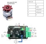
Cooles Projekt! Wie hast du bei den Motoren rausgefunden, an welchem Draht was dranhängt? Die beiden Spulen wird man noch rausmessen können, aber Polarität und Hall wird dann schon schwierig.
 
Ok danke, ja wäre cool wenn du mir bissl was schicken kannst.
Nachdem mich mein Ardumower 2 Wochen lang im Stich gelassen hatte, hab ich meinen alten Automower 308 ausgegraben und überlegt ob ich mit dem was Sinnvolles anstellen könnte.
Da drin ist aber so wenig Platz, dass die Owldrive Treiber nicht reinpassen würden, daher überlege ich ob ichs auch mit einfachen H-Brücken, ein paar Arduino Nanos und einem Raspberry Pi Zero W hinbekomme. Die Antiebsmotoren (5778399-06) haben aber 8 Drähte, was ja eigentlich auf einen 3-Phasigen Motor hindeutet, oder?


PXL_20250514_192837882.jpg
 
Hello Kadaverjoe,
I'm currently launching my 265 ACX with the Owlrobotics kit.
I had the same problem as you with the Raspberry Pi 5. I burned two of them.
I reported it to Bernd, and he's going to exchange a Pi 5 for an Orange Pi. This should fix the problem.

In the meantime, I have a Pi 4 in stock and I'd like to use it (I saw that you solved your problem like this).
But it doesn't work; I can't compile the program.
I didn't have this problem with the Pi 5.
Is there a modification to be made?

Sincerely
 
Hello Reihtaug,

It should work with a Pi 4 without any problems. What is the problem during compiling? I had no problem with that.
Oh and one more thing: I don't need the UBEC for external powering anymore. Try to start it first without a UBEC. It should work fine now. The owl-Board will start once, beeps once and then restarts again. Then it should power up properly. If you hear beeps of the owl board again and again, try to disconnect the battery and repower it again.

Let me know if you need help.

Konrad
 
Zuletzt bearbeitet:
I actually don't know if there is a red LED...on the top of the board, there is one permanent red LED and the green one is blinking when it has CAN-connection
I don't see your compilation error. Otherwise please post it in the comment.
 
Zuletzt bearbeitet:
Oben