Du verwendest einen veralteten Browser. Es ist möglich, dass diese oder andere Websites nicht korrekt angezeigt werden.
Du solltest ein Upgrade durchführen oder einen alternativen Browser verwenden.
Du solltest ein Upgrade durchführen oder einen alternativen Browser verwenden.
DENNA-Plattform
- Ersteller pemiso
- Erstellt am
Hi Roland .
As i understand you perfectly know the problem.
For me to solve it the mower need to stay always exactly where the field intensity is minimum so perfectly upper the wire.
I have also two coil possibility but don't try because the arduino Mega is not very fast ,Each 30ms the perimeter mag is not read with one coil , so two coil ?????.
With the slow tracking it's work well perimeter mag is read each 40 ms.
Maybee the Arduino DUE can work better but i am waiting for the next PCB board and then try sunray because i thing it's very good solution, for example we can approch the station with the map so no track on grass .
i agree that it's very good option to follow the wire inside the loop at changing distance to avoid track on the grass (like HVA mower).
Two other solution to detect the station.
1 I view that the perimeter sender use only one output of the MC33926 and maybe the second can be used
to create an other small perimeter around the station or directly a guide wire like the HVA mower use.
2 Also it's possible to put a IR emetter in the station and the recever into the mower,normally it's work at low distance.
The sonar i don't have good experience on it, on the two tianchen mower i have they don't work more than 1 year and not very well.
But as it work very well on car normaly it may work on mower.
For Bumper your solution is cool but do you know the Robomow RL1000 bumper, It's very simple and work perfecly.The problem is i don't know if you can find this solution at low cost, normaly it's used on safety close door, i try to send you a picture.
Thanks.
Thanks for the information.
Regarding the second coil, I think Jürgen has developed an external board for two coils and I programmed code for the due. But if it is working now it could be better to wait for Sunray in order not to waist further time and throw it away afterwards when you want to install Sunray anyway.
I already tried to find out how the Robomow RL1000 bumper is working, but didn't find a disassambly at the internet. The pressure hose is also used in doors, as I find out there are two more solution: 1.) Uses an contact through all the hose, which is not so easy to build by my own, 2.) Use a light barrier which is also not so easy to build in order the hose is not straight.
It would be nice, if you can tell me how Robomow RL1000 bumper works and send me some pictures of the inside.
Hi Stephan.
Near the motors it's protector board.
Perhaps you have reason ,i think i made a test with all stuff switch off.
The IMU is already off
For the odometry ,it's use interrupt so difficult to disable but as there is only one addition in the loop it's not take a lot of time.
Need to be tested.
Near the motors it's protector board.
Perhaps you have reason ,i think i made a test with all stuff switch off.
The IMU is already off
For the odometry ,it's use interrupt so difficult to disable but as there is only one addition in the loop it's not take a lot of time.
Need to be tested.
Hi Roland.
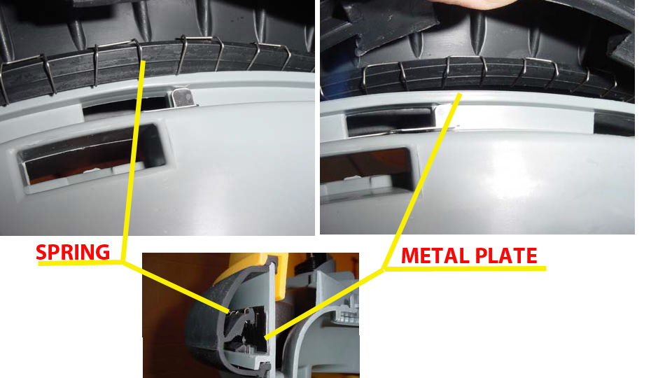
I use 2 RL1000 since seven years and exept the battery life it's actualy the best mower i own .
Bumper work perfectly.
It's not a pressure sensor but only a spring and metal plate with 5mm distance between them.
When the mower hit Something the spring contact the plate .
What i don't understand is that i can't find this very simple solution on the net, only hight cost for safety door with pressure sensor.
Here the picture of the service manual.
Other Idea easy on straight line,more dificult arround the mower.
Put a simple or multiple row of thread all around the mower at 2 cm of the frame and connect the end off each thread at a micro switch or better on a IR sensor .
The thread motion is detect when the mower hit something
Anyway your pneumatic solution and bumperduino are very good idea.
Attachment: https://forum.ardumower.de/data/media/kunena/attachments/3545/RL1000bumper.jpg/
Zuletzt bearbeitet von einem Moderator:
Hi
I try to increase the reading speed of the perimeter receiver so i disable a lot of think but confirm that the problem is in the perimeter reading, it's take near 30ms to compute.
So again I need DEV help in perimeter.cpp
Into this code :
I want to reduce the Samplecount but perhaps simply error or Something i don't understand in the last line, Is there a difference between this lines of code
ADCMan.setCapture(idx0Pin, ((int)255 / adcSampleCount) * adcSampleCount, true);
and
ADCMan.setCapture(idx0Pin, (int)255 , true);
or
ADCMan.setCapture(idx0Pin, 255 , true);
In perimeter tracking i try to put the sample count to 50 instead of 255.
But it's didn't work
Error Perimeter too far each time ??? :evil:
Thanks.
I try to increase the reading speed of the perimeter receiver so i disable a lot of think but confirm that the problem is in the perimeter reading, it's take near 30ms to compute.
So again I need DEV help in perimeter.cpp
Into this code :
Code:
case SRATE_38462: subSample = 4; break;
  }

  // use max. 255 samples and multiple of signalsize
  int adcSampleCount = sizeof sigcode_norm * subSample;
  ADCMan.setCapture(idx0Pin, ((int)255 / adcSampleCount) * adcSampleCount, true);
I want to reduce the Samplecount but perhaps simply error or Something i don't understand in the last line, Is there a difference between this lines of code
ADCMan.setCapture(idx0Pin, ((int)255 / adcSampleCount) * adcSampleCount, true);
and
ADCMan.setCapture(idx0Pin, (int)255 , true);
or
ADCMan.setCapture(idx0Pin, 255 , true);
In perimeter tracking i try to put the sample count to 50 instead of 255.
But it's didn't work
Error Perimeter too far each time ??? :evil:
Thanks.
Hi Boilevin,
the Signal in sigcode_norm[] has 24 fields. The sender send this with 9600baud. When you sample with 38400baud you need at least 96samples to sample the full signal. But I think this will not work, because the crosscorrelation needs the whole signal in the sample array from the beginning and when you read the signal only with one periode, the signal starts in the middle. Under this conditions you have to change the crosscorrelation algorithm. In my opinion, minimum are 192samples.
Look at the functiondefinition:
void ADCManager::setCapture(byte pin, byte samplecount, boolean autoCalibrateOfs){
therefore
ADCMan.setCapture(idx0Pin, (int)255 , true);
ADCMan.setCapture(idx0Pin, 255 , true);
are the same.
ADCMan.setCapture(idx0Pin, ((int)255 / adcSampleCount) * adcSampleCount, true);
adcSampleCount=24*4=96 => 255/96=2 (because of int) => 2*96=192
This means the minimumn is already configured
Another option to increase computation power would be to swap the Arduino Mega Board by a faster Arduino like the Arduino Due - take a look at the perimeter class in the Sunray code (attachment at http://www.ardumower.de/index.php/en/forum/software/827-ardumower-software-sunray) - It uses the Arduino Due that is running at 84 Mhz, so more computation power and also uses the Due integrated DMA-controller for ADC sampling (ADC sampling works 'in background' without CPU).
Hi.
Ok thanks for this change.
I take a look on the kicad to be sure and 2 Questions.
I need also to remove the speaker no or add a BC547 ?
For the charging relay the R18 2K2 is ok or not with the BC547 ?
After confirm i try to put the Due and perhaps test SUNRAY B)
By.
Ok thanks for this change.
I take a look on the kicad to be sure and 2 Questions.
I need also to remove the speaker no or add a BC547 ?
For the charging relay the R18 2K2 is ok or not with the BC547 ?
After confirm i try to put the Due and perhaps test SUNRAY B)
By.
Hi Alexander.
I change the Mega by the due and follow your post on buzzer,flashmem etc...
For the buzzer i don't understand Hardware (i need to keep the original buzzer and add BC547 to make it work or put Something else ???)
I take a look in Sunray and copy the ADCmanager and Perimeter Class on Azurit (little complex for me but it's compile and seems to work.)
Now i can read the perimeter mag each 10 ms so 3*fasters than with the Mega")
Again Thanks.
I change the Mega by the due and follow your post on buzzer,flashmem etc...
For the buzzer i don't understand Hardware (i need to keep the original buzzer and add BC547 to make it work or put Something else ???)
I take a look in Sunray and copy the ADCmanager and Perimeter Class on Azurit (little complex for me but it's compile and seems to work.)
Now i can read the perimeter mag each 10 ms so 3*fasters than with the Mega
Again Thanks.
Hi Alewander.
I follow your post and change the Mega by Due and no problem except:.
You have written:
4.1 The Bluetooth Module HC-05 I run to RX0 / TX0 and VCC = 3,3v (TX and RX of the Bluetooth module already working with 3,3v).
I don't understand why you change the RX and TX port,Maybe it's more easy in your board to connect a new HC05.
Me, i simply remove the R7,R8 and bridge the R6 resistor It's work, the HC05 stay in his place.
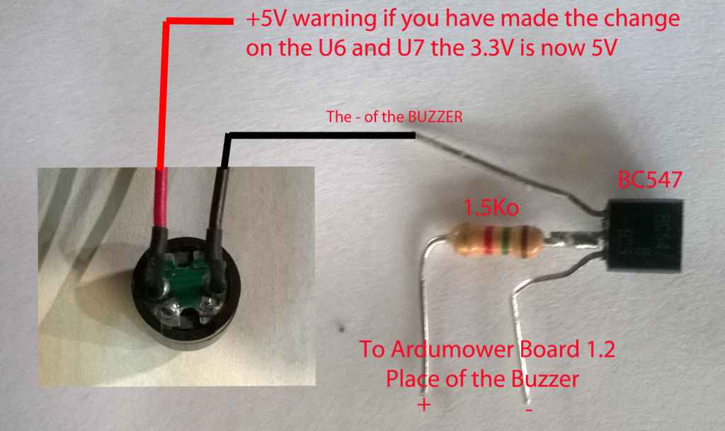
For the Buzzer , no answer so i test on breadboard and it's working
The DUE drain 1mA with this config.
pin 53 -> 1.5 kOhm -> transistor Base
- buzzer -> transistor Collector
ground -> transistor Emittor
+5 V -> + buzzer
Here a picture.
I continue to upgrade Azurit with your Sunray Class
By
Attachment: https://forum.ardumower.de/data/media/kunena/attachments/3545/buzzer.jpg/
I follow your post and change the Mega by Due and no problem except:.
You have written:
4.1 The Bluetooth Module HC-05 I run to RX0 / TX0 and VCC = 3,3v (TX and RX of the Bluetooth module already working with 3,3v).
I don't understand why you change the RX and TX port,Maybe it's more easy in your board to connect a new HC05.
Me, i simply remove the R7,R8 and bridge the R6 resistor It's work, the HC05 stay in his place.
For the Buzzer , no answer so i test on breadboard and it's working
The DUE drain 1mA with this config.
pin 53 -> 1.5 kOhm -> transistor Base
- buzzer -> transistor Collector
ground -> transistor Emittor
+5 V -> + buzzer
Here a picture.
I continue to upgrade Azurit with your Sunray Class
By
Attachment: https://forum.ardumower.de/data/media/kunena/attachments/3545/buzzer.jpg/
Zuletzt bearbeitet von einem Moderator:
schweizer75
New member
hi there,
i am using the denna 600l
has anybody got a picture of the kable connections?
i pulled all mine of due to water failure and i am not shure if they are right cause it seems there is one missing...
regards Schweizer75
Attachment: https://forum.ardumower.de/data/media/kunena/attachments/4587/20180607_100437_2018-06-07.jpg/
Zuletzt bearbeitet von einem Moderator:
Here the picture:
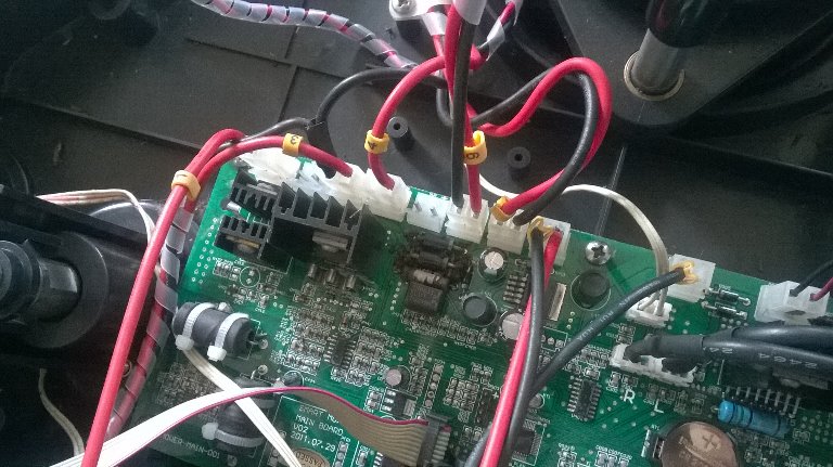
i also have some schema if it can help but need to scan them.
By.
Attachment: https://forum.ardumower.de/data/media/kunena/attachments/3545/WP_20160919_004.jpg/
i also have some schema if it can help but need to scan them.
By.
Attachment: https://forum.ardumower.de/data/media/kunena/attachments/3545/WP_20160919_004.jpg/
Zuletzt bearbeitet von einem Moderator: