DENNA-Plattform

pemiso

Member
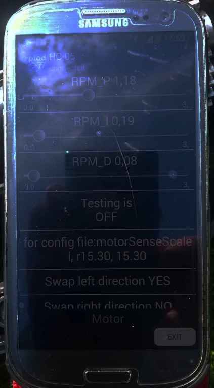
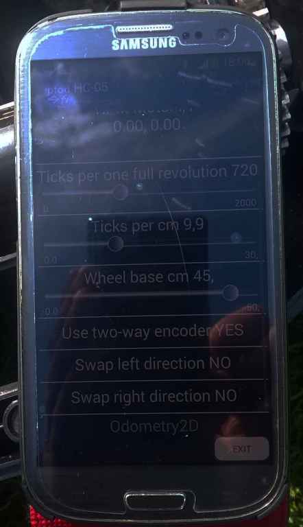
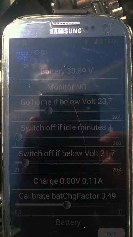
Bin heute den halben Nachmittag im Garten gewesen und habe eine 2. Perimeterschleife provisorisch abgesteckt (25,4 Ohm, 12V / 0,84A). Perimetertracking mit factory default-Parametern für PID funktioniert, aber der Robbi schwänzelt schon ganz schön hin und her.

Gibt es andere Ardumower-Fans, die die DENNA-Plattform benutzen?
Wenn ja, was habt Ihr an den Standard-Parametern geändert?

Ich werde hier jedenfalls nach und nach hier meine DENNA RML-100 Spezifika einstellen ...

Gruß ... Peter
 
Ardumower DENNA-PLATTFORM

Technische Daten

Typ: Denna Typ RML100
Hersteller: Zhejiang Huamao Industrial Co., Ltd., China

Leergewicht: ohne Akkus und Elektronik: 13,5 kg
Maße: 62 x 49 x 30 cm (LxBxH)
Schnittbreite: 27 cm

Radantriebe: 24V Gleichspannungs-Getriebemotor
DONGZHENG Motor 45ZY1006461
angeflanschtes Planetengetriebe 1:90
Hall-Encoder Typ 45ZY68-2450H/60JB90G
12 Impulse je Motorumdrehung
1080 Impulse je Radumdrehung
24 VDC / 22W
Stromaufnahme (Nennbetrieb) 1,6A, 47 r/min bei 3,0 Nm
Stromaufnahme (Leerlauf) 0,5 A bei 56 r/min

Radantrieb: 1:1 Zahnradtrieb (32 Zähne)

Antriebsräder: Raddurchmesser 237 mm
ca. 222 mm Radkörper, Zahnprofilhöhe ca. 7,5 mm
Radabstand 420 mm
14,51 Impulse / cm Fahrweg (ODOmetrie-Parameter!)

Nachlaufräder: 2 x (vorn)

Fahrleistung: Nenngeschwindigkeit ca. 0,58 m/s, ca. 2,1 km/h

Mähwerksantrieb: DONGZHENG 60ZY105-2440
Nennbetrieb 24VDC 60W 4,5 A
Leerlaufdrehzahl 3200 r/min

Mähteller: Kunststoffscheibe
Durchmesser bzw. Schnittbreite 245 mm

Messer: 4 plane Stahlblechmesser mit Montageloch
einseitig schneidend, fest arretiert

Energieversorgung: nicht original, sondern meine Billig-Version:
2 Stück Bleiakku Wentronic Ultracell
12 V, 7 Ah
BxHxL: 65 x 95 x 151 mm
Gewicht: 2,05 kg
Faston 187-4,8mm
 
Hello .
I am new in ardumower , french and speak only french and english.
I have a denna l600 and put a v1.2 board inside.

No big problem to assemble the board and put it in the chassis.

My first question is with the odometry. I change the denna hall sensor to make it work whith arduino.
I add one hall sensor on each motor so now there is 2 hall sensor in each motor .they work fine with a scope.

It s 720 ticks for 1 turn but in other post i see 1080 ?
In pfod the odometry is ok
Result 7200 ticks for 10 turn of wheel but in motor setup i can t find correct PID
When I or D are different of 0 the test motor is false motor slow down and never stop
If P=1 I=0 D=0 it' s work but not very well .
So did you find correct PID for the denna wheel motor.

Now i am going to try with the denna perimeter sender but for the moment the return of the receiver isn t very good.
The scope on the out of the receiver detect the wire but don t make the difference between the inside or ouside of the area and the ardumower soft can't use it.
So if somebody have already done that it will be welcome.

I try to put some picture when i find the way to do it in the forum but a all is explain in german.

Thank you and congratulation for all the staff for the enormous and incredible work achieved.
 
Hi Boilevin,

Why did you add the 2 hallsensors? My mower ist working with the original Denna hallsensors.

Which software version do you use?
Do you use BT connection to Android handy with pfodApp or ArduRemoteApp? It is very helpful to use this to control setup parameters and check sensor signals during test drive.

Did you correctly setup all used sensors in mower.cpp?
 
Hi Boilevin,

choose english GUI in the upper left corner of the page.
To add a photo, for example use the reply button, find "Attachments" in the bottom of edit-window and click "Add file"
choose a picture (name will be inserted) an click the "insert button"
IMG_9029.jpg


click "Submit button"
Attachment: https://forum.ardumower.de/data/media/kunena/attachments/1035/IMG_9029.jpg/
 
Zuletzt bearbeitet von einem Moderator:
Hi Boilevin,

Is tested standard PID parameters for Perimeter Tracking. It is not optimal but works.
Try to use perimeter sender V2. The signal is ardumower special. Study the WikiPages for details.

I am currently in changing my setup to latest version Azurit 1.05, ahve to repair my broken perimeter wire and will test the new setup during weekend.

Will be back here with report of results next week ...

See you.

Peter
 
Thank you peter.
I don't undestand why,but the original hall sensor don t work and i going to see that my motor is not the same as yours.

So when i open the odometry there is a second place to put a hall sensor so i did it.
I replace 4.7 Ko by 10 Ko resistor on one motor but nothing change.
I remove the small capacitor and no difference also.

So i try to put photo on the forum( Sorry if it did not work but it the first time)

Here the Original Denna ODO
ododenna.jpg

Here is after change the 2 sensor
odomodif.jpg


And here the result whith Oscilloscope
Odometrymoteur1.jpg


I use Hc05 whith pfod and it work very well.
The ticks count is correct

But if i use P I D original The motor is in (resonance) i don't know the term in English .
Motor left go fast stop and after it s the right etc.
I try whithout the wheel so whit no charge perhap it s the problem ?

I give more information after more test in last post.
Thanks
Attachment: https://forum.ardumower.de/data/media/kunena/attachments/3545/ododenna.jpg/
 
Zuletzt bearbeitet von einem Moderator:
Hi Boilevin,

did you set "twoWayOdometrySensorUse = 1; // use optional two-wire odometry sensor" in mower.cpp?
 
Hi Peter

No in mower.cpp.
i use 1.04 azurit no change in code simply by pfod set odometryuse=Yes and 720 ticks by turn.

But when i set this option in Pfod then it's very bad the wheel don't stop or move by saccade.

Whithout odometrie all is good the PWM work fine.

With odometrie the PID is only working whit P=1 I=0 D=0 ???


1 i am going to set twoWayOdometrySensorUse = 1 in mower.cpp but normaly in Pfod i try it
2 i am going to test twoWayOdometrySensorUse = 1 and 1440 tick by turn
2 I am going to test only with one sensor
3 I test with charge on the motor to avoid big accel

thanks a lot
 
I am going to see in the wiki

IMPORTANT: PCB v0.5/1.2 are missing pull-up resistors! You need to add them yourself at the PCB.

I understand this but in the Denna Odometrie there is a 10 Ko or 4.7 Ko.
I's 5V-- 10Ko -- out and direct to the link on the board.

Do you think i need to add a second 10Ko pull-up ???
 
Hi Peter thanks for your help.

After test i need to invert the Pinodometryleft and Pinodometryleft2 direct the wire and not in pfod like i test a lot of time .


odo.jpg


After the motor and odometrie work fine with this param:

motor.jpg


odo_param.jpg


Sorry for the picture quality.


I have looked at the code and don't understand why the twowayodometryuse exist.

I view it's use to know if the Wheel go forward or backward
but in reality the soft control the motor direction by the speed and motorPWMCurr positive or negative and set the Pinmotormowdir

if (twoWayOdometrySensorUse) {
// pin2 = HIGH? => forward
if (odometryLeftState2) odometryLeft += leftStep; else odometryLeft -= leftStep;
else {
if (motorLeftPWMCurr >=0) odometryLeft ++; else odometryLeft --;
}
}


Maybe it's better for me to change the code and use the pinodometryleft2 or right to double the ticks value and have a better PID performance.

A last Strange think in Pfod in the setting and batterie :
the batterie voltage is wrong.
It's 27.2V with mutimetre 26.9 in Arduino console and 30.89 in PFOD and 2.6V on Pin AD2.
The ADC calibration seem to be correct because the arduino console is OK.


batterie.jpg


If someone know the real twowayodometryuse function and the difference between Pfod and console result for the Batterie it may help to understand.

Now i'am going to order the Perimeter sender V2 because the Denna one is not compatible.

Thanks a lot
Attachment: https://forum.ardumower.de/data/media/kunena/attachments/3545/odo.jpg/
 
Zuletzt bearbeitet von einem Moderator:
Hi all

Question:
In the code there are double declare in input with or without PULLUP I think i need to remove one if i use button or sensor.

In my DENNA L600 Bumper are Button so INPUT and Dropsensor are Hall sensor but i need to add a 10Ko resistor between Out and VCC to work with arduino mega so INPUT again whithout PULLUP no ??

Maybee it's what is written in german remark ?

// bumpers
pinMode(pinBumperLeft, INPUT);
pinMode(pinBumperLeft, INPUT_PULLUP);
pinMode(pinBumperRight, INPUT);
pinMode(pinBumperRight, INPUT_PULLUP);

// drops
pinMode(pinDropLeft, INPUT); // Dropsensor - Absturzsensor - Deklariert als Eingang
pinMode(pinDropLeft, INPUT_PULLUP); // Dropsensor - Absturzsensor - Intern Pullab Widerstand aktiviert (Auslösung erfolgt gegen GND)


Thanks and good luck for the new developpement.
 
Hi Boilevin,
For my understanding 2wayOdometry is needed in case of using 2-channel incremental sensors.
But if I understand you right, you only use the additional added hallsensor and not both, the original DENNA and your own sensor? so I think, you have a 1wayOdometry.

Regards ... Peter
 
Hi peter.

I use the Twowayodometry and 2 channel incremental sensor.
Like you can see in picture the 4 wires are connected and the Twoway-encoder is set to Yes so normaly in Interrupt the Odometryleft2 is used.

But in fact my question is Why option Twowayodometry

In the Code:

if (twoWayOdometrySensorUse) {
// pin2 = HIGH? => forward
if (odometryLeftState2) odometryLeft += leftStep; else odometryLeft -= leftStep;
else {
if (motorLeftPWMCurr >=0) odometryLeft ++; else odometryLeft --;
}
}


If i understand The motorLeftPWMCurr is used to set Forward or Backwark so why testing if the Wheel go forward with the second sensor because it's obligation or the motor driver is crashed.

Maybe it's better to use it to increase the ticks odometry.

I hope you can understand what i mean it' s difficult for me in English.

For the moment i think the only interest of the 2wayodometry in the code is when the motor are not used but why, or to test the wiring ?

Sorry if it's a bad interpretation of the code.

By
 
Umbau der Docking-Station DENNA auf Ardumower:

Integration des Perimetersenders in das DENNA-Gehäuse

1. Einbau der Kontroll-LEDs und der Ladebuchse für den 24V-Lader aus dem Shop
2. Einbau der Anschlußklemmen für den Perimeterdraht
3. Verlagern der Sicherung vom Senderboard ins Gehäuse der Ladestation

image.jpeg


Von innen sieht das dann so aus (links ist unten). Der Motortreiber ist noch nicht montiert. Habe ihn leider zu spät bei Markus bestellt. Die LEDs sind auf einem Experimentierboard montiert und vo innen mit den Köpfen nach außen durchgesteckt. Die Verbindung zum Senderboard erfolgt über eingelötete Buchsenleisten und Flachbandkabel. Die Buchsenzuordnung 1:1 zur Reihenfolge im Senderboard habe ich etwas unelegant "gefädelt".

image_2016-07-06.jpeg


Die Verbindungen von Perimeterkabeln und Stromversorgung zum Senderboard erfolgt über Federklemmböcke (geniale Teile, gibt's u.a bei Rei...lt). Um die dicken Leistungskabel daran anzuklemmen, löte ich mir meine Spezialstecker:

Kabel abisolieren
image_2016-07-06-2.jpeg


Aderendhülse auffädeln
image_2016-07-06-3.jpeg


image_2016-07-06-4.jpeg


"Pfosten" ziehen
image_2016-07-06-5.jpeg


"Pfosten" einsetzen und verlöten
image_2016-07-06-6.jpeg


Ein wenig Isolation schadet nie
image_2016-07-06-7.jpeg


Es klemmt!
image_2016-07-06-8.jpeg


Ein anderer Kandidat für den Steckerpfosten wäre dieser her:

image_2016-07-06-9.jpeg

Attachment: https://forum.ardumower.de/data/media/kunena/attachments/1035/image.jpeg/
 
Zuletzt bearbeitet von einem Moderator:
Hi peter.
Very good job and i hope it's work for you.

For me i have a big problem and spent a lot of time to test but the sender or the
receiver don't work ???

Here picture of the sender


1.jpg


2.jpg


3.jpg


4.jpg


I try whith 12 Ohm 50W resistor in serie with 20 or 150 ml perimeter wire.
In all case the signal seem to be OK on the arduino console 8 V 0.66 A

sender.jpg


And at the M1OUT the Scope

senderscope.jpg


So for me the sender seems to be OK.

But at the out of the receiver there is Nothing flat line at 2.5 Volt
I test whith a second receiver --> same problem
I connect all GND on the receiver --> same problem

I have a small signal only when the perimeter wire touch the coil but Nothing at 1 cm ??

Here the receiver

receiver2.jpg


receiver3.jpg


you speak in a post about The duty cycle and RV1 pot But i don t really understand what is it .

If it s work for you Can you tell me what the Volt signal and wave i need to have on the output of the receiver when the wire perimeter is at 1cm and 10cm or more of the coil because in the wiki there is signal wave but never size(output voltage) and Nothing about the coil and perimeter wire distance ??

Thanks if you can help me.
Attachment: https://forum.ardumower.de/data/media/kunena/attachments/3545/1.jpg/
 
Zuletzt bearbeitet von einem Moderator:
Good evening Boilevin,

Please check your receiver: the amplifyer should be set to maximum. To do this the potentiometer should be set to "full open".
As I had my problems with the perimeter, I found that I turned the knob of the potentiometer to one end but the wrong one - I set it to minimum.

So test to turn the poti other way round or in the middle for your next test :)

I hope this helps ...

Kind regards .. Peter
 
Oben