Du verwendest einen veralteten Browser. Es ist möglich, dass diese oder andere Websites nicht korrekt angezeigt werden.
Du solltest ein Upgrade durchführen oder einen alternativen Browser verwenden.
Du solltest ein Upgrade durchführen oder einen alternativen Browser verwenden.
DENNA-Plattform
- Ersteller pemiso
- Erstellt am
Hi again,
I just come out of the garden: at first I tested my 2nd just now completed sender. Ok 100%!!! Now I wil disassemble my DENNA to take out the receiver for a photo. It will take some minutes because it is very warm and my 2nd job in the garden was lawn mowing. Today I jogged with my benzin mower and made it in 2 hours") All the way I had a dream: Ardumower
All the way I had a dream: Ardumower
I just come out of the garden: at first I tested my 2nd just now completed sender. Ok 100%!!! Now I wil disassemble my DENNA to take out the receiver for a photo. It will take some minutes because it is very warm and my 2nd job in the garden was lawn mowing. Today I jogged with my benzin mower and made it in 2 hours
All the way I had a dream: Ardumower ok here are the pictures:
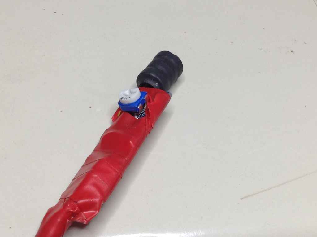
dressed for isolation because he lives in an old edding aluminium house
Naked backside: white wire is GND connector. C3 is bridged!!!
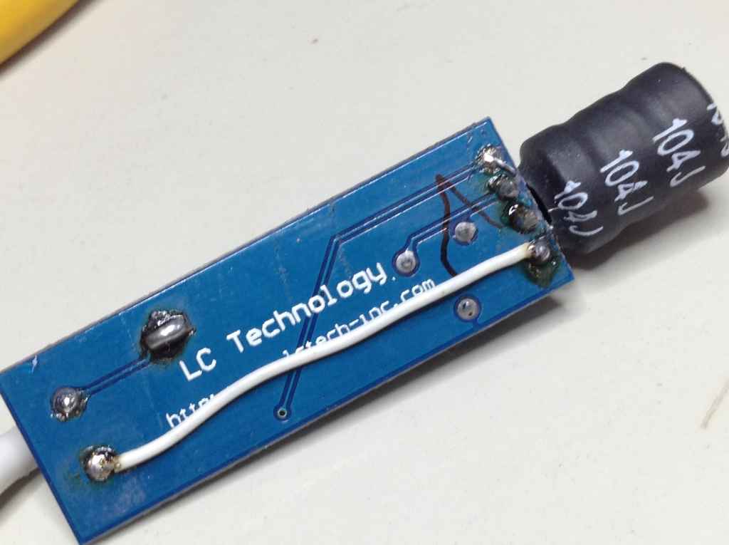
and the chocolade side. I took out C3 to be slim enough for the Edding-House
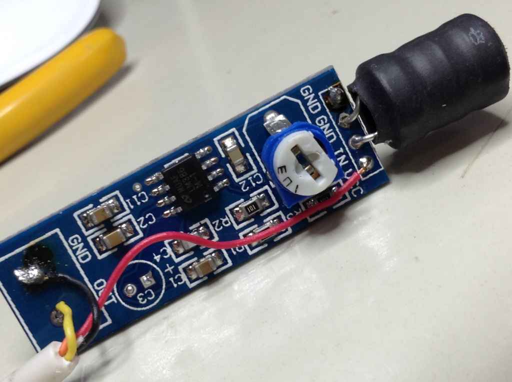
the cable for mower connection is an old mouse cable: thin, flexible and 3 wires. Signal is yellow, red and black Vcc and GND
Attachment: https://forum.ardumower.de/data/media/kunena/attachments/1035/IMG_2602_2016-07-09.jpg/
dressed for isolation because he lives in an old edding aluminium house
Naked backside: white wire is GND connector. C3 is bridged!!!
and the chocolade side. I took out C3 to be slim enough for the Edding-House
the cable for mower connection is an old mouse cable: thin, flexible and 3 wires. Signal is yellow, red and black Vcc and GND
Attachment: https://forum.ardumower.de/data/media/kunena/attachments/1035/IMG_2602_2016-07-09.jpg/
Zuletzt bearbeitet von einem Moderator:
Hi Peter
THANK YOU It's exactly what i need to view .
The only difference is that you remove the C3 but as it's bridge i don't understand and the GND is not totaly bridge
like i did.
To be sure i wire the receiver exactely like you and make a test.
But maybe it's not the receiver the problem .
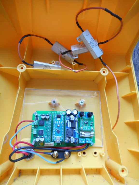
I use four 3 Ohms 30W resistor in serie to have 12 Ohms maybe it's why the signal is OK at the output of the Motor driver but not in the perimeter wire ???.
I think i am going to buy a 10 or 12 Ohms 50 Watt resistor to test
I hope it's the problem
Thank You again.
Attachment: https://forum.ardumower.de/data/media/kunena/attachments/3545/DSCN0269.jpg/
THANK YOU It's exactly what i need to view .
The only difference is that you remove the C3 but as it's bridge i don't understand and the GND is not totaly bridge
like i did.
To be sure i wire the receiver exactely like you and make a test.
But maybe it's not the receiver the problem .
I use four 3 Ohms 30W resistor in serie to have 12 Ohms maybe it's why the signal is OK at the output of the Motor driver but not in the perimeter wire ???.
I think i am going to buy a 10 or 12 Ohms 50 Watt resistor to test
I hope it's the problem
Thank You again.
Attachment: https://forum.ardumower.de/data/media/kunena/attachments/3545/DSCN0269.jpg/
Zuletzt bearbeitet von einem Moderator:
Hi Boilevin,
you are welcome
is THIS your test surrounding?
You should take a 2..3 m wire for the test, because I would think that the disturbing effects of DC-DC-Converter and motordriver are HEAVY if you put the receiver coil near to it!!!
Resistance should be ok. Which voltage do you have at DC-DC-Converter Out+ / Out-? Should be about 8..9V.
In case of very low perimeter resistance you could get high current and DC-DC-converter will become hot. To reduce current in such cases you can switch from double to single amplitude in the sender code.
Set „#define USE_POT“ to „1“ in sender code. Now you are able to setup Duty Cycle und Duty PWM at the left potentiometer. By doing this the perimeter current can be adjusted and checked via serial monitor.
Did you a ADC-Adjustage? Perimeter sender must be off. Choose ADC-setup via pfodApp.
Senderstatus is controlled by 5 LEDs.
From left to right: 24V supply, 5V supply (both green), perimeter state perimeter 1 and 2 (both duo leds, completely ignore them!) and the very important yellow one for perimeter fault signal!
The green ones must be on for voltage supply 24V and arduino 5V.
Perimeter Fault: the yellow LED is
off when perimeter broken or disconnetcted
on when perimeter is connected and minimum current is flowing
blinking if perimeter is connected but current too low
Pin13 LED on Arduino nano is
on when perimeter i connected and minimum current >0,03A.
Off when perimeter is not connected or broken.
Hi.
During the last 2 week end i did a lot of test :evil: .
My Tianchen Outdoor perimetre 150 m 5 Ohm + 12 Ohm resistor.
Indoor in the garage 10 m approx 2 Ohm + 12 Ohm serie resistor.
At the DC DC out now iT's 8V and Pericurrent near 0.66 A (same in WIKI).
I made a test with the arduino console, When i increase the Output DC/DC Voltage until a get 1 ampere in Pericurrent
The voltmetre say 12/13 V on the DC/DC output.So i think it's normal But nothing on the receiver?
Tomorrow I try to define USE_pot to 1 , now i understand why the 2 pot on the sender board have no effect if set to 0.
On the mower i made ADC calibration with Pfod each time i change something.
Pin13 Led on Nano and the Perimetre fault (I put a green led but not Yellow i invert whith 5V, I hope it's not important) are ON when the perimeter is ok and OFF when break.
Duo Led are not connected and 24V, 5V are ON.
Tomorrow i try to make a screen capture in Pfod Plot Perimeter so you can see the problem.
I also take Screen capture of the OsciloScope in the output of the receiver
I really don't understand I test 2 receivers and the same result.
Hope this Week end will be the good.
PS i see you work on the battery charging in other post.
For me I use DENNA Li ion battery and actualy charge them directly with the charger (red and green led when finish),so i try to not use the INA169 and the Mega to control charging.
Only use the "Yellow led current" to switch On the relay when in the station and let the charger work.
Concerning the RTC module i connect it and it work on Pfod but for the moment Schedule the mowing is dream :lol:
Thank you for translation of the led color and Duty because i never see in wiki or forum in English
By and have a good Week end.
Hi.
The 2 receiver i use come from Ardumower shop and the coil are in the Delivery so i hope there are the correct one.
In the console i have Duty=1.00 and view in some post Duty=100 ????
I'm going to see 1.00 is the same thing that duty 100 %
Maybe i have to change some value in the code but for me if it's work with the original code for you with PCB v1.2 and sender v2 then there is problem in my board or config.
By
Hi.
Now I understand the problem.
You help me when you tell that your coil is 104J,the 2 coils i receive are 154J and that is the problem.
To be sure i reuse the old coil of my Denna board and all is different.
With 154J coil In setting perimeter, Value where 0,3,-2,-4,0 or something like that and in plot Sign is flat.
With my old coil Value is now 1200 -1200 and sign change each time when i move uppon the wire.
So for Peter Thank you and for maratronics shop GRRRR!!!! :evil:
It's joke but maybe it's better to inform them but i don't know how and who need to be informed that the receiver they send is not working with this coil..
By and good week end.
Hi Boilevin
Super - one problem less ...
I will contact Markus to inform him about the coil problem ...
By the way: there is a standalone testreceiver you can build with an arduino nano, the receiver and the software .
I found it useful especially to check the perimeter walking around with my testing stick (electronic in plastic watertube connected to my laptop (usb / serial monitor).
Have a nice rest of the weekend!!!
Peter
Thanks.
Next step
Control if all is OK with the old Coil because this time the signal seems to be too important and for a reason i ignore there are perimeter error ,But i need to test better and certainly change value in setting perimeter to adapt this coil.
But in all case i prefer this big signal instead of nothing with 154J.
By
Hi
This Week end i take time to make some test and the result is not very good in the perimeter tracking but good in Auto Mode the perimeter is detected and the mower work.
Strange thing in the bumper, the mower take 1 second to stop and change dir.
Maybee there are parameters to change in the Wheel motor to stop direcly whitout PWM like in the Motor Mower testing : the start is soft PWM but the stop is immediat and very strong and it's what the mower need when hiting obstacle.
I also note that when the mower change dir in perimeter "hiting" or bumper there is a lot of pause between each changing status from REV ROLL etc...
I thing i need to take time to find the correct PID tracking and have a "smoother" following wire.
If somebody know were are there parameters it help but in all case i need to have a look in the code to find solution for better working.
Thank Peter and all the staff.
BY
I
Hi Peter.
I note that i can detect the cutting wire with a standalone receiver, but if maratronics send me the same coil it can't work.
By the way i have tianchen and robomow parfectly working in my garden so no problem with perimeter wire.
Thanks again and good luck with your new mower project.
I note that i can detect the cutting wire with a standalone receiver, but if maratronics send me the same coil it can't work.
By the way i have tianchen and robomow parfectly working in my garden so no problem with perimeter wire.
Thanks again and good luck with your new mower project.
I finish to adapt the ardumower board into my denna chassis.
The most important change is in the permeter tracking because i can't find correct PID to work smoothly so need to make some change in the code.
Not perfect because too slow.
Here picture and video link
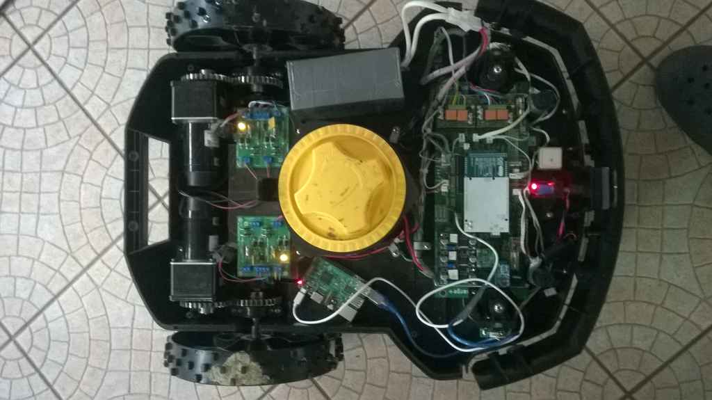
tracking
Docking
If somebody have a faster result it's can help me.
Attachment: https://forum.ardumower.de/data/media/kunena/attachments/3545/dennapi.jpg/
The most important change is in the permeter tracking because i can't find correct PID to work smoothly so need to make some change in the code.
Not perfect because too slow.
Here picture and video link
tracking
Docking
If somebody have a faster result it's can help me.
Attachment: https://forum.ardumower.de/data/media/kunena/attachments/3545/dennapi.jpg/
Zuletzt bearbeitet von einem Moderator:
Hi Boilevin,
good job for using one coil. This is smooth. I think you will never find the correct PID to work smoothly because the field intensity has a bump on both sides of the wire. So when you go from above the wire to the outside, the field intensity increases, then you got a maximum and then the intensity decreases. Same when going to the inside, but with negative amplitude. Therfore two coils work better. The inside coil will then stick near the wire while the outside coil is more away from the wire.
When you use one coil in my opinion best solution is to drive inside the perimeter. When near station go over the wire and dock. The advantage is also, that you don't have to drive the same track every time.
This is what I must do in order of my Geoborader. I want to use a beam to realise that I am near the station. I have the parts for infrared, but had problems with my first bumper, so this I have to solve first. Another option could be to generate a beam with sonar or radio. Maybe you have got some experiance with sonar?