Du verwendest einen veralteten Browser. Es ist möglich, dass diese oder andere Websites nicht korrekt angezeigt werden.
Du solltest ein Upgrade durchführen oder einen alternativen Browser verwenden.
Du solltest ein Upgrade durchführen oder einen alternativen Browser verwenden.
compass 5983 imu gy88a
- Ersteller andri85
- Erstellt am

@andri85 Thank you for replying. I have to ask where did you find that Wire.h? It's a bit weird place to have the mappings. In ardumower project they should more likely be in imu.h/cpp. Anyways the correct mappings are below. I have confirmed them from the specifications and the code provided by the manufacturer. I believe the MMC5883MA_DYNAMIC_RANGE and MMC5883MA_RESOLUTION are not useful in anyway, but the readings of x,y,z axis need to be adjusted with the MMC5883MA_OFFSET and MMC5883MA_SENSITIVITY, to get correct readings.
Also you will not need the MMC5883MA_ADDR_WRITE and MMC5883MA_ADDR_READ, the wire library handles them for you if you are using the commands provided by i2c.ccp like:
I have the compass working in "2D", perfect 1degree resolution. I can also read the product id and temperatures from the chip. But only problem is now that the current tilt compensation code for the compass is not working. Calibrations done, but no help. Even just a couple of degree tilt can change the heading 10-100 degrees. I believe the problem is in the imu.cpp "void IMU:update()" -method, but haven't found out the correction yet.
Correct register mapping is as follows (
Also you will not need the MMC5883MA_ADDR_WRITE and MMC5883MA_ADDR_READ, the wire library handles them for you if you are using the commands provided by i2c.ccp like:
Code:
I2CwriteTo(MMC5883MA, INT_CTRL0, 0x08);  // set command

I2CreadFrom(MMC5883MA, STATUS, 1, (uint8_t*)buf2); // read 1 byte from status register
I have the compass working in "2D", perfect 1degree resolution. I can also read the product id and temperatures from the chip. But only problem is now that the current tilt compensation code for the compass is not working. Calibrations done, but no help. Even just a couple of degree tilt can change the heading 10-100 degrees. I believe the problem is in the imu.cpp "void IMU:update()" -method, but haven't found out the correction yet.
Correct register mapping is as follows (
C++:
//*****************************************************
// MMC5883MA Register map
//*****************************************************
#define XOUT_LSB    (0x00)
#define XOUT_MSB    (0x01)
#define YOUT_LSB    (0x02)
#define YOUT_MSB    (0x03)
#define ZOUT_LSB    (0x04)
#define ZOUT_MSB    (0x05)
#define TEMPERATURE (0x06)
#define STATUS      (0x07)
#define INT_CTRL0   (0x08)
#define INT_CTRL1   (0x09)
#define INT_CTRL2   (0x0A)
#define X_THRESHOLD (0x0B)
#define Y_THRESHOLD (0x0C)
#define Z_THRESHOLD (0x0D)
#define PROD_ID1    (0x2F)

#define MMC5883MA_OFFSET      32768
#define MMC5883MA_SENSITIVITY   4096
//*****************************************************
// MMC5883MA Register map end
//*****************************************************@andri85 This sounds like my struggle at the start. I always get mag ~2000 when near wire but just 5 meters from wire it can go very low. I have the perimeter sender and all parts from the original complete ardumower kit from the shop. The sender is just not too good. I used to have Ambrogio L300 for years and with same cables (just the same that is sold on ardumower shop) the L300 never had any trouble with the signal, but you really have to work to get Ardumower going. And I have professional multimeter and the loop resistance is very well where it should be.
Edit:
And I have also maxed out the voltage to have just shy of the max 1A as the wiki says. Plugged in my values for the example formula and solved right voltage and adjusted voltage with multimeter:
Current: I = U / R = 8 Volt / 12 Ohm => 0.7 Ampere
Perimeter sender (English) – www.wiki.ardumower.de
wiki.ardumower.de
Edit end.
Edit 2:
If you are having issues with perimeter, one more important thing is to change the Timed-out if below smag to 80 or so. The original 300 is just too much when long way from the wire. And increase the trigger timeout slightly to 150 or so (you should experiment on your scenario).
Edit 2 end
You can help the situation with changes in perimeter.cpp. Try at own risk.My commit comments for this:
"Magnitudes over 500 can be always counted as reliable. 1000 is a bit too much.
Increasing the signal counter from 3 to 15 will allow much better perimeter handling on low signal areas eg. middle of the yard and away from perimeter wire."
C++:// perimeter inside/outside detection if (mag[idx] > 0){ //signalCounter[idx] = min(signalCounter[idx]+1, 3); signalCounter[idx] = min(signalCounter[idx]+1, 15); } else { //signalCounter[idx] = max(signalCounter[idx]-1, -3); signalCounter[idx] = max(signalCounter[idx]-1, -15); } boolean Perimeter::isInside(byte idx){ // if (abs(mag[idx]) > 1000) { if (abs(mag[idx]) > 500) {
In my case the mower stops and turns always near the middle of the mowing area without any transition in the attached plot, only cnt changes.
So would it help in my case to change the signal counter in perimeter.cpp? Or is there anything else I can change to stop this behavior?
Anhänge
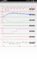
First you need to be sure it's a perimeter issue.In my case the mower stops and turns always near the middle of the mowing area without any transition in the attached plot, only cnt changes.
So would it help in my case to change the signal counter in perimeter.cpp? Or is there anything else I can change to stop this behavior?
Try to deactivate the mow motor into Setting Mow and test the mower without mow motor running .
If the trouble in the middle area has gone.You need to add noise filter on your mow motor.(Not really easy).
For Compass : IT'S NOT POSSIBLE TO USE A COMPASS LIKE HMC5883 or MMC5883 WITH ACCURACY inside the mower (If you have a smartphone try to test compass software for store and move your phone near the mower
and you understand immediately the issue)Only GYRO /ACCEL are accurate for YAW finding.