Du verwendest einen veralteten Browser. Es ist möglich, dass diese oder andere Websites nicht korrekt angezeigt werden.
Du solltest ein Upgrade durchführen oder einen alternativen Browser verwenden.
Du solltest ein Upgrade durchführen oder einen alternativen Browser verwenden.
compass 5983 imu gy88a
- Ersteller andri85
- Erstellt am
hello bernard. I am trying these days to make it go on the lawn but it does not work as it should. For the compass I managed to paper as I wrote above. when I have ultrasound and / or the perimeter turned on it has a strange behavior. it advances 2 meters, stops, turns, and advances another 2 meters, and then endlessly. deactivating both works well, cuts in a straight line and does not stop. on the station I still have the azurit firmware. can it create problems? what if i find the right version to upload? I saw that on your code there is written sender heltec, can I load it on the arduino nano even if it includes a display and the wifi module? I also tried to compile it but it gives me errors, perhaps because I don't have the right libraries !!
@markor.
What is the code in the txt file (It's OK or it's Something you find on the net that didn't work)
@andri.
I can only help with AZURITBER.

 github.com
On sender the azurit firmware is the correct one if you use the sender from the shop.
github.com
On sender the azurit firmware is the correct one if you use the sender from the shop.
Do you have a Pi connected ?
If Yes check the console and all is easy to understand.
If No what is the perimeter mag into arduremote setting Perimeter (Normaly 2000 near the wire ).
Also Check the sonar into setting sonar.
For compass
If new GY88A use the code from branch GYRO-ONLY
it's also possible to use a GY87.But need change in the code ,so tell me is you have one and i can create a new branch on GitHub for it.
What is the code in the txt file (It's OK or it's Something you find on the net that didn't work)
@andri.
I can only help with AZURITBER.
Boilevin/AzuritBer
Ardumower full odometry version. Contribute to Boilevin/AzuritBer development by creating an account on GitHub.
github.com
Do you have a Pi connected ?
If Yes check the console and all is easy to understand.
If No what is the perimeter mag into arduremote setting Perimeter (Normaly 2000 near the wire ).
Also Check the sonar into setting sonar.
For compass
If new GY88A use the code from branch GYRO-ONLY
it's also possible to use a GY87.But need change in the code ,so tell me is you have one and i can create a new branch on GitHub for it.
The change from + to - is not OK at all if the mower is not Moving.if the robot is stopped. could it affect?
The mag need to be negative if Inside the perimeter and positive outside.
The change from + to - explain that the mower reverse etc ….
It's possible to see this change from + to - normaly only on small Mag value <300 when the mower is at the middle of a big mowing area.
How is set your mowing area?
what is the wire lenght ?
Resistor value of the wire ?
Sense and voltage on the sender ?
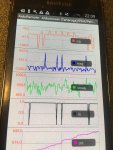
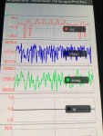
on plotters you can see even better.
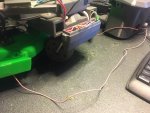
I am currently on a table with a thread about 2 meters long.
this afternoon, however, in the garden it was more or less 20-30 meters long.
the resistance is from 8 ohm 100watt
mowing area is line
I'm sending the sender with the 29.4v 3A charger
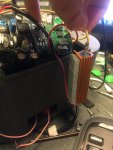
Is it normal for resistance to get very hot? I also put small heatsinks on it, it will reach 60 °.
I am currently on a table with a thread about 2 meters long.
this afternoon, however, in the garden it was more or less 20-30 meters long.
the resistance is from 8 ohm 100watt
mowing area is line
I'm sending the sender with the 29.4v 3A charger
Is it normal for resistance to get very hot? I also put small heatsinks on it, it will reach 60 °.
Anhänge
???mowing area is line
Resistance hot is Ok.
2 meter is not OK for test it's better 10 meter minimum on a correct circle.
But mag value is very low if upper the wire; I read 2000 on all my area with 9V on DC/DC out sender .
I hope the receiver coil is Vertical and the poti on it is at the max,also the shunt capacitor etc... Chech again WIKI
Hi Markor. the only way to solve the problem was to wallpaper. I found a gy 801 module that mounted the hmc5883 compass. I cannibalized it by removing the other modules that did not interest me and I connected it to another i2c port. so the compass works well
Funny, but I was just as well looking for the gy-801 in Amazon. And there is actually a separate HMC5883L chips available also. I'm starting to think that's the best way to go. I have now wasted 5 days of my time for this piece of chip and it just can't produce any reliable readings what so ever. So disappointed as my original chip worked great, but the 2 more "gy-80" I ordered are pretty useless with the damn MMC5883L. I have tried the the examples I have found and also tried just about everything in the chip's specifications, but nothing usable. I have tried continuous measurement, I have tried measure once, I have set different output resolutions in internal control 1, I have set different frequenzies for continuous measurement in internal control 2, I have tried reading the status register to get values when they are ready, tried setting interrupts, tried accounting the offsets by set-measure1-reset-measure2 procedure, etc etc etc. The links below are no use at all. Everytime when I get close to 0-360 heading readings it's just showing 150 then I turn it 180 degrees and it says 40 and after a while 120 or something. I'd wallpaper them too, but I actually want my money back.

danielarico/SodaqONEv3-MMC5883MA
Arduino compatible code for the Sodaq ONE v3 board, to read magnetic field from the external 3-axis magnetic sensor MMC5883MA through I2C, using the Wire Arduino library. The data is sent to The Th...
github.com
@markor.
What is the code in the txt file (It's OK or it's Something you find on th
For compass
If new GY88A use the code from branch GYRO-ONLY
it's also possible to use a GY87.But need change in the code ,so tell me is you have one and i can create a new branch on GitHub for it.
@bernard The code was provided by Markus from Marotronics and it should work and read the MMC5883MA compass, but it really doesn't. When I upload the sketch the buzzer just beebs continuously and in console I get sometimes readings that might look ok (but the code is not trying to calculate heading etc), but then I try it at some other time and all axis are giving -234253442 or 3242342 or whatever.
I do realize now that I propably need to by the HMC5883L chip separately, but I'm pretty disappointed to have two chips that doesn't meet the specs when sold and delivered. But if it's just one file please throw the code change you made for GY-87 and I'll take a look. Might order it then..
Edit:
Code:
First run of the MMA5883MA Sketch (the text file) sometimes giving good looking values:
x: -509  y: 90  z: -2022
x: -505  y: 91  z: -2022
x: -509  y: 92  z: -2024
x: -507  y: 92  z: -2025

But just reopen the console and it may give good values on just 1 axis or all can be like this:

x: 268774412  y: 549664  z: -1559074975
x: 268774412  y: 549664  z: -1559074975
x: 268774412  y: 549664  z: -1559074975
x: 268774412  y: 549664  z: -1559074975
So far no matter what test's I have done by the specs can over come this. Powering off the ardumower totally doesn't help eather. It seems totally random to get sensible looking data or total garbage.
Zuletzt bearbeitet:
hello bernard. I am trying these days to make it go on the lawn but it does not work as it should. For the compass I managed to paper as I wrote above. when I have ultrasound and / or the perimeter turned on it has a strange behavior. it advances 2 meters, stops, turns, and advances another 2 meters, and then endlessly. deactivating both works well, cuts in a straight line and does not stop. on the station I still have the azurit firmware. can it create problems? what if i find the right version to upload? I saw that on your code there is written sender heltec, can I load it on the arduino nano even if it includes a display and the wifi module? I also tried to compile it but it gives me errors, perhaps because I don't have the right libraries !!
@andri85 This sounds like my struggle at the start. I always get mag ~2000 when near wire but just 5 meters from wire it can go very low. I have the perimeter sender and all parts from the original complete ardumower kit from the shop. The sender is just not too good. I used to have Ambrogio L300 for years and with same cables (just the same that is sold on ardumower shop) the L300 never had any trouble with the signal, but you really have to work to get Ardumower going. And I have professional multimeter and the loop resistance is very well where it should be.
Edit:
And I have also maxed out the voltage to have just shy of the max 1A as the wiki says. Plugged in my values for the example formula and solved right voltage and adjusted voltage with multimeter:
Current: I = U / R = 8 Volt / 12 Ohm => 0.7 Ampere
Perimeter sender (English) – www.wiki.ardumower.de
Edit end.
Edit 2:
If you are having issues with perimeter, one more important thing is to change the Timed-out if below smag to 80 or so. The original 300 is just too much when long way from the wire. And increase the trigger timeout slightly to 150 or so (you should experiment on your scenario).
Edit 2 end
You can help the situation with changes in perimeter.cpp. Try at own risk.
") My commit comments for this:
My commit comments for this:"Magnitudes over 500 can be always counted as reliable. 1000 is a bit too much.
Increasing the signal counter from 3 to 15 will allow much better perimeter handling on low signal areas eg. middle of the yard and away from perimeter wire."
C++:
  // perimeter inside/outside detection
  if (mag[idx] > 0){
    //signalCounter[idx] = min(signalCounter[idx]+1, 3);
    signalCounter[idx] = min(signalCounter[idx]+1, 15);
  } else {
    //signalCounter[idx] = max(signalCounter[idx]-1, -3);
    signalCounter[idx] = max(signalCounter[idx]-1, -15);
  }

boolean Perimeter::isInside(byte idx){
//  if (abs(mag[idx]) > 1000) {
  if (abs(mag[idx]) > 500) {
Zuletzt bearbeitet:
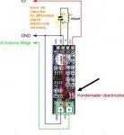
solved ... I didn't realize that on wiki it was written to bypass the c3 capacitor on the amplifier. I bypassed it, the signal almost doubled and I no longer had positive peaks
@andri85 Great you found that one! The instructions to solder the sender/receiver are not very clear. Anyways, I have done that too and it didn't unfortunately help me in real environment. I guess you are still experimenting with a small loop, so if you or anyone else run to any troubles with larger areas hopefully the above instuctions may provide help. I just added a few more critical tips to it.
Zuletzt bearbeitet:
@bernard Yes, I know smooth mag (smag) is *trying* to do that, but it's not working well enough when your mag drops quickly just few meters from the perimeter (<300).
I am actually now using 30 in signalcounters and running very smooth. I know this basicly "disables" the perimeter sensor on areas where there simply is not signal, but it doesn't matter as whenever we get close to the border line we will use the actual MAG instead of the smag.
My perimeter is closed loop of course like everyone's. I don't care anymore why the signal is so crappy. When close to the border we use the actual MAG and when at the middle of the yard let the robo do it's thing, no matter what perimeter signal says. I have never had it run more than 20cm out of the area. Right above the line mag is about 2200, so it will know pretty instantly that it has crossed to the dark side. I'm so glad this is open source.
@bernard I'm using https://github.com/Ardumower/ardumower . I forked it around 21st may 2019 from the master. Been doing ton load of code since then, but haven't got around to make any push requests or update from the main. I guess I should check the latest commits, but I highly doubt there is nothing in software side that would help the situation. My yard is very big, and while the perimeter wire resistance is within specs there can be places with 10-15m from closest perimeter. And when the mag goes down hugely just after few meters, so does the smag at the center spots of the yard. But any assistance and teaching on the subject is welcome! I know there is a whole lot of code that I just haven't been able to figure out yet.
btw
- My mover can detect from mower power longer grass and circle with widening radius to mowe a bit more effectively the longer grass areas.
- My robo can detect if it's stuck by GPS speed. You know those soft bumbs with soft ground and the mover just keeps grinding forwards against bush while actually stationary. Not mine, if we going straigth and gps speed goes below 0,2, we correct the situation pretty fast.
- Impoved the sonar detection of obstacles
- And I'm now putting some final touches on some more advanced GPS stuff
- like returning to charge with GPS (need the damn compass chip working)
- automatic areas and counting how many times long grass is found per area and how much time spent on each area and focus on certain areas based on that
- mowing without perimeter with standard parts, highly experimental still, but I have always at least 8 satellites visible so I'm getting like 20-40cm accuracy which I think I can boost with some other means near the borders.
I guess I should check the latest commits, but I highly doubt there is nothing in software side that would help the situation. My yard is very big, and while the perimeter wire resistance is within specs there can be places with 10-15m from closest perimeter. And when the mag goes down hugely just after few meters, so does the smag at the center spots of the yard. But any assistance and teaching on the subject is welcome! I know there is a whole lot of code that I just haven't been able to figure out yet.btw
- My mover can detect from mower power longer grass and circle with widening radius to mowe a bit more effectively the longer grass areas.
- My robo can detect if it's stuck by GPS speed. You know those soft bumbs with soft ground and the mover just keeps grinding forwards against bush while actually stationary. Not mine, if we going straigth and gps speed goes below 0,2, we correct the situation pretty fast.
- Impoved the sonar detection of obstacles
- And I'm now putting some final touches on some more advanced GPS stuff
- like returning to charge with GPS (need the damn compass chip working)
- automatic areas and counting how many times long grass is found per area and how much time spent on each area and focus on certain areas based on that
- mowing without perimeter with standard parts, highly experimental still, but I have always at least 8 satellites visible so I'm getting like 20-40cm accuracy which I think I can boost with some other means near the borders.
Zuletzt bearbeitet:
GPS is M6N ??
For perimeter signal :
When the mower is near the wire (less than 50 cm the Smag is >400) ,so in this case you can consider a good Isinside.
If the mower is far from wire SMAG is <400 so do not check the in out transition.
It's only how it's work (Into the code it's more complex)
For perimeter signal :
When the mower is near the wire (less than 50 cm the Smag is >400) ,so in this case you can consider a good Isinside.
If the mower is far from wire SMAG is <400 so do not check the in out transition.
It's only how it's work (Into the code it's more complex)
@bernard GPS is GY-GPS6MV2, came with the standard full set from ardumower shop.
@andri85 I am just too stubborn I guess. Couldn't let it go with the MCC5883MA. I have been in contact with the manufacturer and the key thing to produce meaningful results was the offset and sensitivity, which need to be applied to the readings of each axis as shown below.
I can now get 0-360 degrees heading on even plane (if I only calibrate the compassa around z axis 360 degrees). But whenever I calibrate it 360 around all 3 axis I start getting really weird readings like 40 degrees, turn 10 degrees and it's 150, etc. Calibration and everything seems to work great, but trying to read and learn that tilt compensated compass readings algorithms are really a handful...
C++:
    #define MMC5883MA_OFFSET      32768
    #define MMC5883MA_SENSITIVITY   4096

    //measurement 1
    I2CwriteTo(MMC5883MA, INT_CTRL0, 0x01);
    delay(1);

    byte mask = 0x01;

    I2CreadFrom(MMC5883MA, STATUS, 1, (uint8_t*)buf2);
    while ( (buf2[0] & mask) != 1 ) {
      I2CreadFrom(MMC5883MA, STATUS, 1, (uint8_t*)buf2);
    }

    I2CreadFrom(MMC5883MA, 0x00, 6, (uint8_t*)buf);

    float x = (uint16_t)(buf[1]<< 8 | buf[0]);
    float y = (uint16_t)(buf[3]<< 8 | buf[2]);
    float z = (uint16_t)(buf[5]<< 8 | buf[4]);

    x = ((float)x - MMC5883MA_OFFSET)/MMC5883MA_SENSITIVITY;
    y = ((float)y - MMC5883MA_OFFSET)/MMC5883MA_SENSITIVITY;
    z = ((float)z - MMC5883MA_OFFSET)/MMC5883MA_SENSITIVITY;