compass 5983 imu gy88a

andri85

Member
Ciao ragazzi
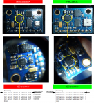
Sto cercando di eseguire l'Imu Gy88a con Azuritber. il firmware includeva il gy88. la differenza sta nella bussola che da hmc 5883l diventa hmc 5983. Ho provato a sostituire l'indirizzo 0x1E con 0x30 e la scritta da 5883L a 5983 ma spostando la bussola su arduremote mi segna sempre 90 °. sapresti cosa cambiare Allego il file originale con il sensore 5883L.
grazie
 

Anhänge

  • AzuritBer-master1.zip
    10,9 MB · Aufrufe: 6
Hello guys
i am trying to run the imu gy88a with azuritber. the firmware included the gy88. the difference is in the compass that from hmc 5883l becomes hmc 5983. I tried to replace the address 0x1E with 0x30 and the writing from 5883L to 5983 but on arduremote moving the compass always marks me 90 °. would you know what to change. I attach the original file with the 5883L sensor.
thank you
 
Hi.
Are you sure that the 5883 and 5983 have not the same adress (0x1E) is the hexadecimal one and 0x30 is decimal.
Do you use PCB1.3 ?
Have you shunt the AD0 on GY88 ?
see:
 
connecting it on an arduino with the sketch for detecting the i2c address and giving me 0x30. yes I put ad0 at 3.3v, in fact the address of the mpu6050 is 0x69. but tonight looking at the gy88a sensor I saw that above the integrated compass there is written 5883 and not 5983, but I am trying to get a microscope to look better ... I think it is a mmc5883ma ... to try what I should modify on the sketch beyond the address of the i2c bus ?? I saw in the datasheet that there are many other addresses but I don't know where to go to edit..I have read the whole post of jussip, indeed I can say that I am doing his own project :)68EF724F-718F-4C86-AA70-15F12010272F.jpeg
 
Code from master branch is old ,so please use the code from RFID branch.
I think the IMU is OK.
See attached file for I2c scan of PCB1.3 with RTC and GY889.

To be sure all is OK you need to start the mower with PC communication and check in the Arduino IDE console the 50 first line to see if there is an error.
Compare to attached file
Do not forget to change the console direction into mower.h (see ardumower.ino first line description)
and for test #define Enable_DueWatchdog to false into mower.h
 

Anhänge

  • i2c adress gy88 rfid rtc.txt
    524 Bytes · Aufrufe: 15
  • IMU Gyro Calibration console example.txt
    2,1 KB · Aufrufe: 14

Anhänge

  • i2c scanner.txt
    648 Bytes · Aufrufe: 8
  • watchdog false consolle.txt
    1,4 KB · Aufrufe: 9
  • watchdog true consolle.txt
    1,5 KB · Aufrufe: 5
  • hmc5883.png
    hmc5883.png
    4,2 MB · Aufrufe: 12
On GitHub in the middle left of the screen ,you can change branch from master to RFID (the last version of code is rfid)
Certainly you have the new version of HM5883 and the code need to be adjust to use it.

I Don't have this kind of ship so it's not possible for me to test some part of code.

I take a look on datasheet and try to tell you what you can test.
 
Hi
Can you test this first test code and show me the console result at 115200 bps
Be sure that the PCB is ON with battery.
 

Anhänge

  • mmc5883ma.zip
    1,5 KB · Aufrufe: 12
OK.
Here second test:
try to uncomment line 83
or comment line 82
Move the IMU to see if the result show Something OK:oops:
 

Anhänge

  • mmc5883 test2.zip
    1,8 KB · Aufrufe: 11
Here it is.
During both tests I turned the sensor 2 times clockwise and 2 times anticlockwise. I noticed that the yaw degree has a jump from 7/8 degrees to 160 degrees very quickly even turning the sensor slowly.
In the txt i also put the commented lines so as not to have translation errors
 

Anhänge

  • MMC5883MA-TEST 2-COMMENT LINE 83.txt
    18,4 KB · Aufrufe: 8
  • MMC5883MA-TEST 2-COMMENT LINE 82.txt
    14,3 KB · Aufrufe: 5
Is it possible to test with the IMU out of the mower at 50cm from all metal parts or magnet ?

Line 180 remove the range and resolution and test again or Simply change the range value
C#:
float ans = (float)(MSB << 8 | LSB);
 
Zuletzt bearbeitet:
To do the tests 50 cm away from all the metal parts I stretched the wires 80 cm and fixed the imu on a piece of wood.
I did the same tests as before and I also tried to comment on the row 180 and change the values of resolution and range but the results failed. With the commented line 180 it always gave me 0 and changing the resolution and range values it always gave me 44-45.
Then I don't know if it could be useful I did a test by rotating the imu in pitch instead of yaw and I saw that the yaw degree value changed.
however these are the results:

ps. I am also attaching a photo to understand how I fixed the IMU so as not to disturb.
 

Anhänge

  • MMC5883MA-TEST 2-COMMENT LINE 83 AND 180.txt
    7,9 KB · Aufrufe: 4
  • MMC5883MA-TEST 2-COMMENT LINE 82.txt
    30,4 KB · Aufrufe: 2
  • MMC5883MA-TEST 2-COMMENT LINE 82 AND MODIFIED 25-26.txt
    13,3 KB · Aufrufe: 0
  • MMC5883MA-TEST 2-COMMENT LINE 83 AND MODIFIED 25-26.txt
    10,7 KB · Aufrufe: 1
  • MMC5883MA-TEST 2-COMMENT LINE 83 MOVEMENT PITCH .txt
    20,4 KB · Aufrufe: 1
  • MMC5883MA-TEST 2-COMMENT LINE 83.txt
    23,1 KB · Aufrufe: 1
  • unnamed.jpg
    unnamed.jpg
    1,1 MB · Aufrufe: 15
With the commented line 180 it always gave me 0
Sorry : line 180 you need to replace it by this one and not Simply comment it
float ans = (float)(MSB << 8 | LSB);
to remove the range and see if the X Y and Z value are on the 16 bits resolution (65535).
rotating the imu in pitch instead of yaw
You can change the axes into line 114 (to see if axes are not in correct direction)
the y_val with z_val or all other possibility.
test1 : yaw = scalePI(atan2(z_val, x_val))
test2 : yaw = scalePI(atan2(y_val, z_val))

In all case i try to add the test code Inside the imu.cpp and you can test with the calibration process.
Other possibility is to remove totaly the compass in the code and use only the Gyro
Because in reality it is use only for absolute position in bylane mowing
 
Into GitHub you can find a new branch named GYRO only.
The compass is not use now and the Gyro is set to 0 when the mower is into station ,so the mower north is now the station heading.
The Only issue can be in the bylane mowing the drift can make the lane not perfectly parallel over time.
 
Into GitHub you can find a new branch named GYRO only.
The compass is not use now and the Gyro is set to 0 when the mower is into station ,so the mower north is now the station heading.
The Only issue can be in the bylane mowing the drift can make the lane not perfectly parallel over time.

Anything new for this one? I'm stugling to get the compass work as the latest gyro chips that came are now using the MMC5883MA, which totally screws everything up. I have been developing my own branch for quite a some time and playing with GPS areas etc and I really need the compass to work. I already was looking help at the end of last summer (september or so) and at that point noone even knew the gyro had the HMC5883L replaced with the MMC5883MA!

During the winter I got an email from Markus from Marotronics that contained some test code for the MMC5883MA. I only got back to this project now as the summer is coming and grass is starting to grow again. In 2 days I have had a very little luck getting any sensible readings from the compass. And it seems my problems are just like @andri85 's. If I get any readings the reading are VERY slow to change etc.

I must ask is this gyro chip a "china version" with "china version" compass or is this the current official gyro chip with the official compass chip. And if it is official compass chip why am I not finding successful implementations with ardumower? (yes, might be my shortcomings for the last 2 days of trying)
 

Anhänge

  • MMC5883MA.ino.txt
    1,5 KB · Aufrufe: 17
Oben