Du verwendest einen veralteten Browser. Es ist möglich, dass diese oder andere Websites nicht korrekt angezeigt werden.
Du solltest ein Upgrade durchführen oder einen alternativen Browser verwenden.
Du solltest ein Upgrade durchführen oder einen alternativen Browser verwenden.
Arctic Hare mod by Jussi
- Ersteller jussip
- Erstellt am
Some assembling and printing has been made.
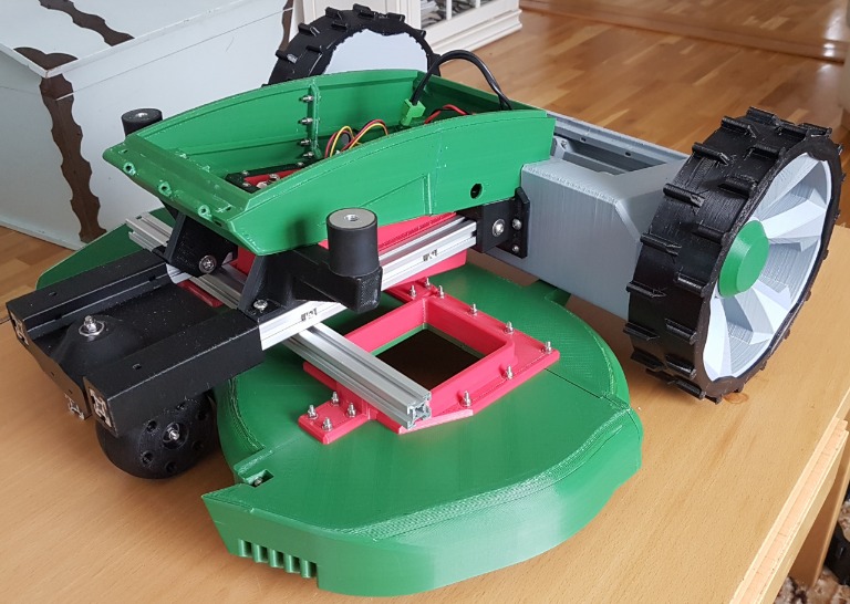
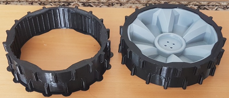
First printed tpu-tire was 100% solid and I didnt get it to wheel. Next one is printed two 0.7 perim./loop and 20% infill. With hair dryer I managed to get it on place

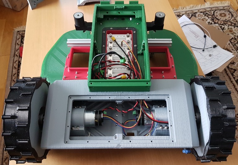
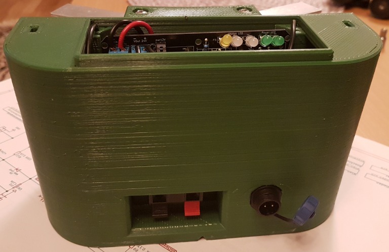
Casing for bumperduino and us-sensor pcb's. Holes are made for glands

Under pcb box lid is mounts for zerocam, zero, gps, dht22, rain sensor pcb, raspi 3b and zip ties.
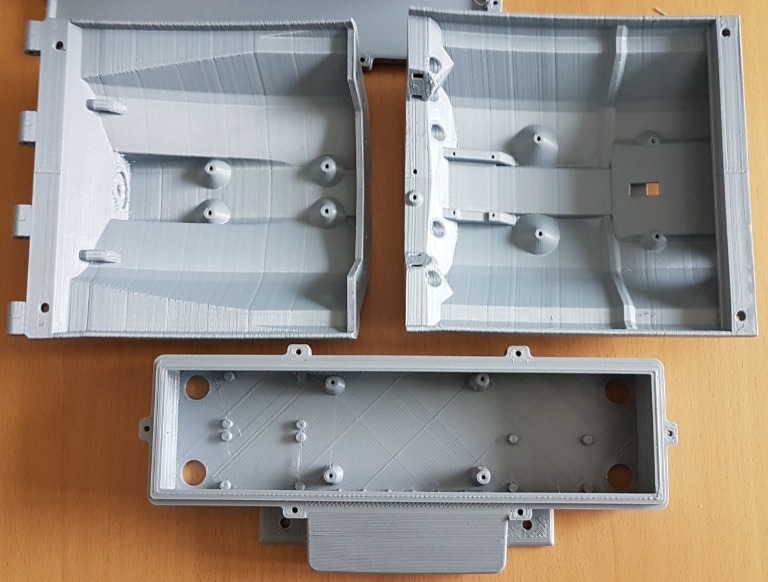
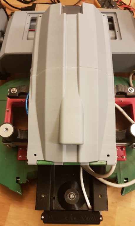
Mowing motor box and lid

Attachment: https://forum.ardumower.de/data/media/kunena/attachments/4741/2019-03-2012.24.43.jpg/
First printed tpu-tire was 100% solid and I didnt get it to wheel. Next one is printed two 0.7 perim./loop and 20% infill. With hair dryer I managed to get it on place
Casing for bumperduino and us-sensor pcb's. Holes are made for glands
Under pcb box lid is mounts for zerocam, zero, gps, dht22, rain sensor pcb, raspi 3b and zip ties.
Mowing motor box and lid
Attachment: https://forum.ardumower.de/data/media/kunena/attachments/4741/2019-03-2012.24.43.jpg/
Zuletzt bearbeitet von einem Moderator:
New due and new issue to solve. I'm wondering charging/battery voltage measurement. ADC calibration is done and battery/charger factors are setted and measurements are correct but when charger is connected to p42 also battery voltage rise to same level and charging never start. (difference between charger and battery is just d73 forward voltage drop) Why there is d73? Thinking if I remove d73 issue is solved, or is it?
Hi.
I have exactly the same behaviour on 2 PCB1.3 but it's not really a problem.
If you do all the test with a correct charged battery it's normal that the charge did not start but with a low bat normaly the voltage rise slowly and the mower have time to detect the low bat and charge can start.
I did not use the Azurit firmware but you can find the reading bat voltage location and if i remember there is a low pass filter and maybe Simply change the factor to have a different behaviour but i think it's not necessary to change electronics on the board.
By.
Today when charged battery first time, battery voltage was 23.5 and it didnt started charging before I changed batfactor only -0.5v off but charging didnt stop with that setting.
Looking schematics (page 1 and 30) and I really dont understand why there is that bypass line from p42 to "batterieeingang"
Looking schematics (page 1 and 30) and I really dont understand why there is that bypass line from p42 to "batterieeingang"
Certainly it did not solve your issue but it's not the batfactor that i only change .
It's the low pass filter.
I use value 0.05 and not 0.01 (check line 625 in robot.cpp)
I also check the battery only each 500ms and not 100 so the voltage increase slower when reach the station (check line 606 in robot.cpp) .
For the electronics i have not look because it's always work without any issue.
The Timer can also cause bug in the charging.
For the charging start i have also change this in the code (line 1611 remove the delay in station)
Certainly this help in your case but Don't know why this delay for azurit ?
Code:
case STATE_STATION:
      // waiting until auto-start by user or timer triggered
      if (batMonitor) {
        if ((chgVoltage > 5.0) && (batVoltage > 8)) {
          if (batVoltage < startChargingIfBelow) { //read the battery voltage immediatly before it increase
            setNextState(STATE_STATION_CHARGING, 0);
          }
Certainly this help in your case but Don't know why this delay for azurit ?
This is from master azurit
Removing delay makes sense but what purpose is adding
before checking that batvoltage is below setting
Code:
case STATE_STATION:
     // waiting until auto-start by user or timer triggered
      if (batMonitor) {
        if (chgVoltage > 5.0) {
          if (batVoltage < startChargingIfBelow && (millis() - stateStartTime > 2000)) {
            setNextState(STATE_STATION_CHARGING, 0);
          }
Removing delay makes sense but what purpose is adding
Code:
&& (batVoltage > 8)")
I tested b channels too, same result about 350. Actually its 700 because divider is soldered. Theres also setting in mower.cpp
Code:
#if defined (PCB_1_3)
		#define DIVIDER_DIP_SWITCH  2             //  sets used PCB odometry divider (2=DIV/2, 4=DIV/4, 8=DIV/8, etc.)
		odometryTicksPerRevolution /= DIVIDER_DIP_SWITCH;        // encoder ticks per one full resolution
Is this another divider, so that actual ticks are now divived by 4 (2 and 2)?
If I put gps to system it keeps then rtc in utc time?
Charging station ready for testing. Only front covers are not printed yet, I have some unsolved bumper related things going on before printing those

Aluminium contacts are spring loaded and ready for copper contacts with magnets inside. Probably using 12 mm copper capillary hats there..

New BMS installed

Also lid is installed.

Attachment: https://forum.ardumower.de/data/media/kunena/attachments/4741/2019-03-3121.13.47.jpg/
Aluminium contacts are spring loaded and ready for copper contacts with magnets inside. Probably using 12 mm copper capillary hats there..
New BMS installed
Also lid is installed.
Attachment: https://forum.ardumower.de/data/media/kunena/attachments/4741/2019-03-3121.13.47.jpg/
Zuletzt bearbeitet von einem Moderator:
Gps is not use into azurit so for me it is better to not connect it.
Also it seems that there is trouble on the PCB 1.3 to connect it .(Rx and Tx ?...)
For the time and date normaly the rtc work like a charm.
If you want a good robot mower you need to spend time on the full automatic cycle ( mowing , tracking, docking,charging ) without human intervention.
I follow you and Paddy on your 3D printing work and many congratulation for your work.
I have not see for the moment the docking and charging parts but certainly you work on it.
Docking something like this way

Attachment: https://forum.ardumower.de/data/media/kunena/attachments/4741/docking2.png/
Attachment: https://forum.ardumower.de/data/media/kunena/attachments/4741/docking2.png/
Zuletzt bearbeitet von einem Moderator: