Arctic Hare mod by Jussi

jussip

Member
Arctic Hare mod printing and building thread.

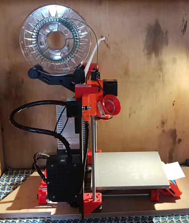
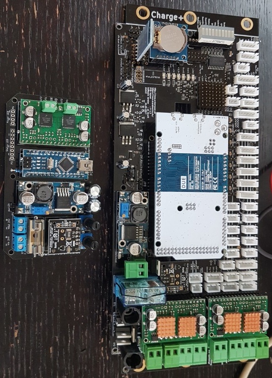
Some progress has been made. Electronics kit has not arrived yet.

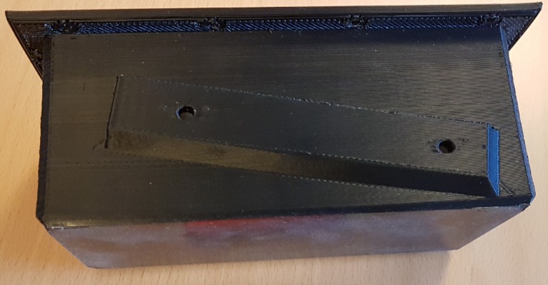
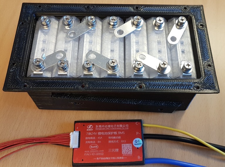
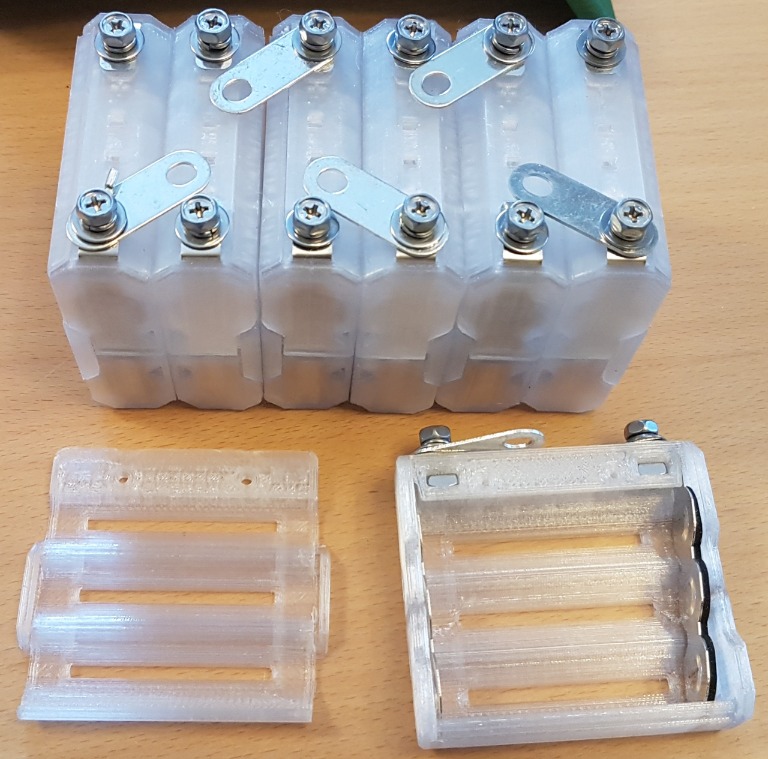
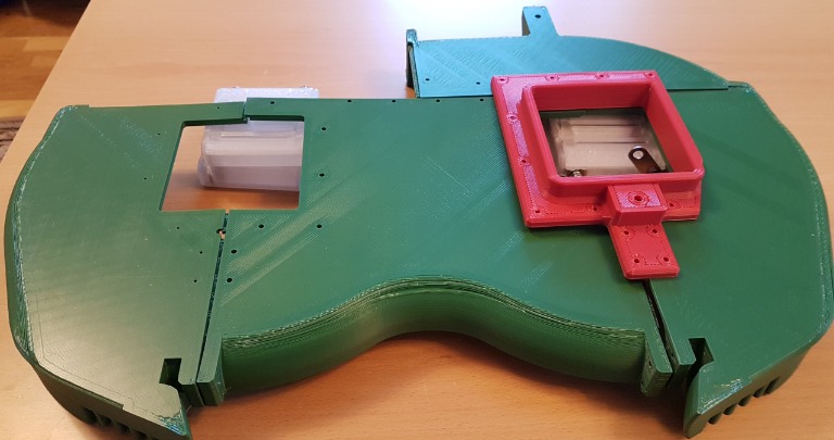
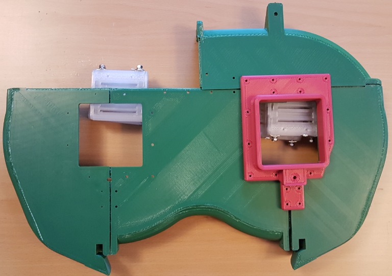
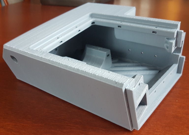
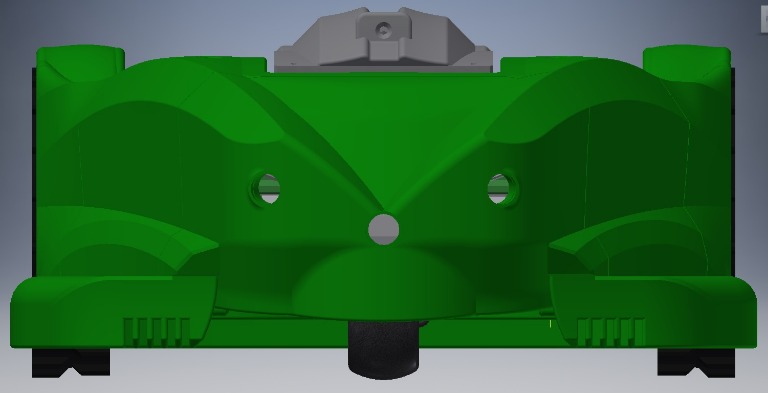
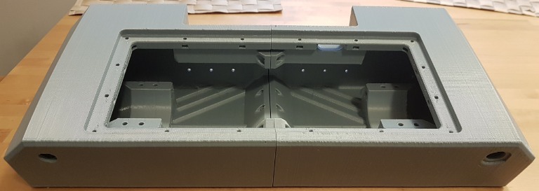
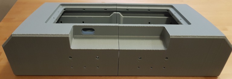
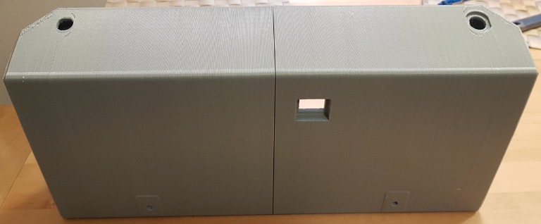
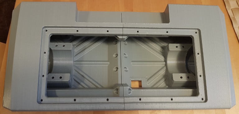
Battery box and NESE modules for 18650 cells. Plan is use samsung 35E 3500mAh cells (3p7s)
2019-02-2616.12.05.jpg

2019-02-2616.11.51.jpg

2019-02-2616.01.09.jpg


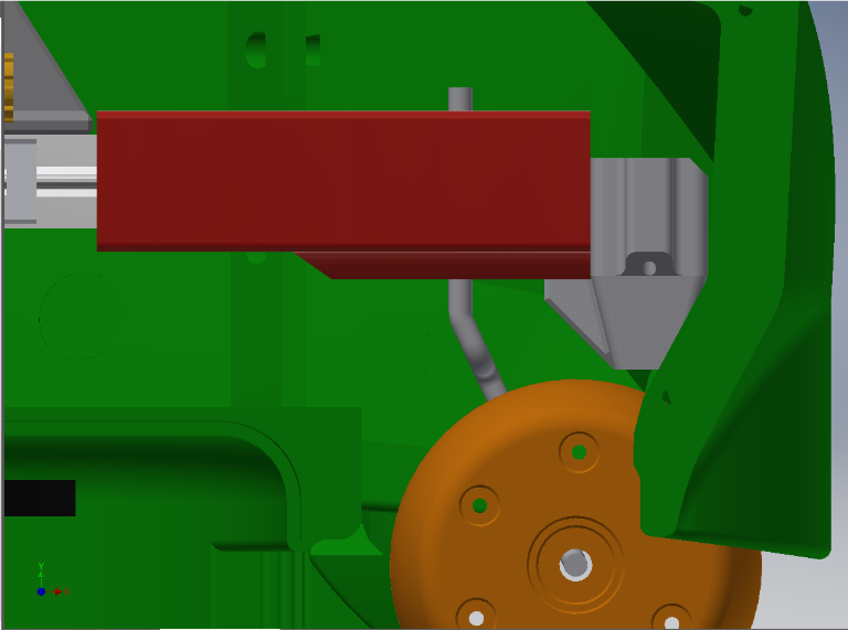
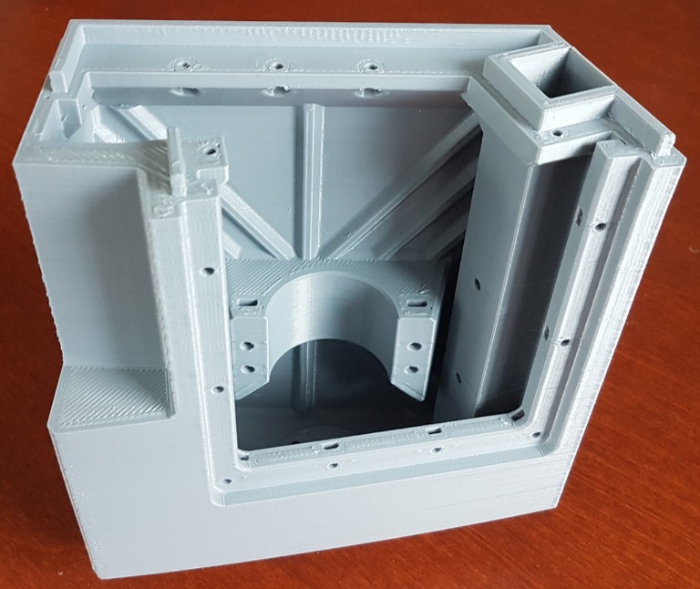
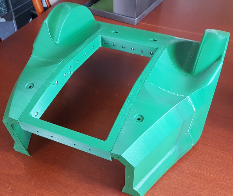
Front wheel assembly and perimeter receiver box
2019-02-2616.01.26.jpg


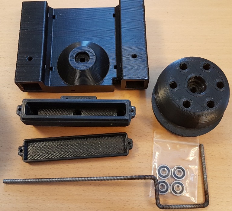
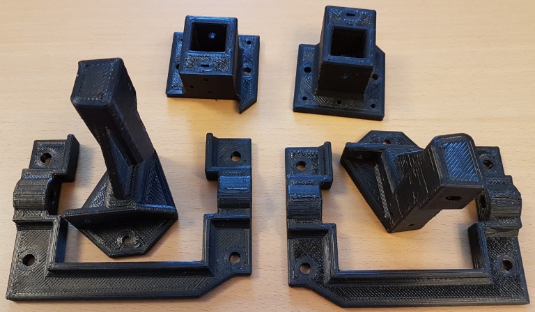
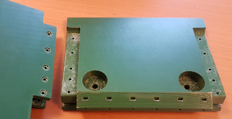
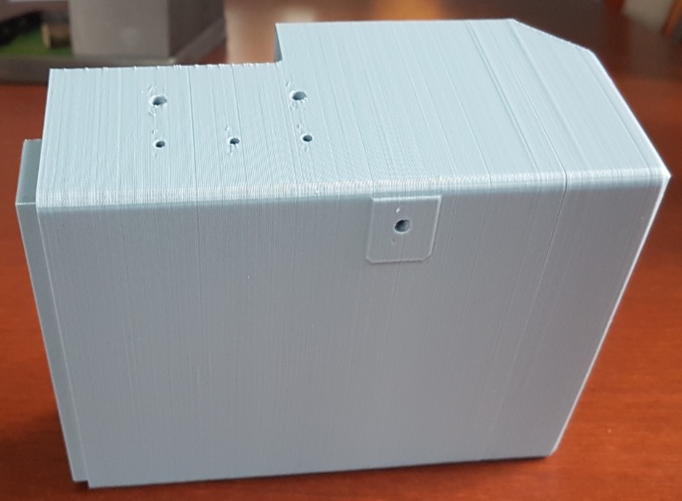
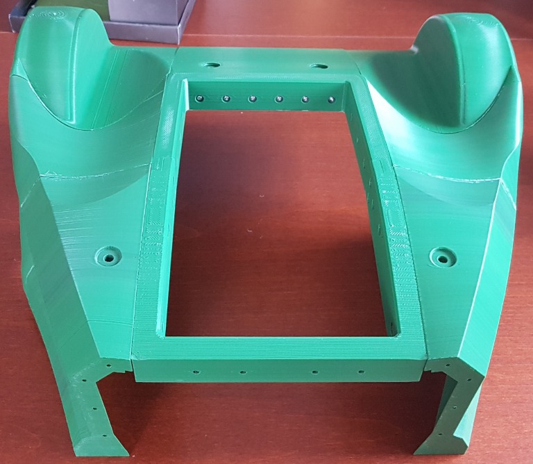
pcb box brackets and mowing motor brackets
2019-02-2616.03.09.jpg


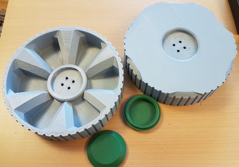
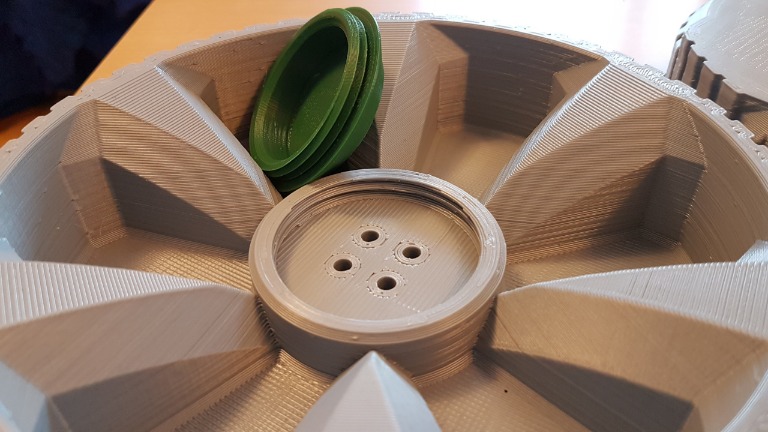
Rear wheels and wheel caps
2019-02-2616.01.35.jpg

2019-02-2616.02.01.jpg


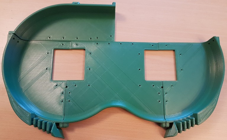
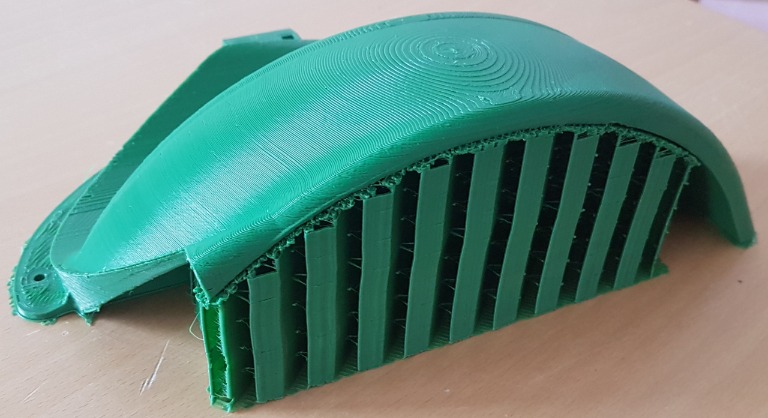
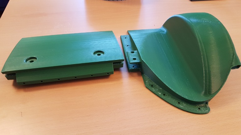
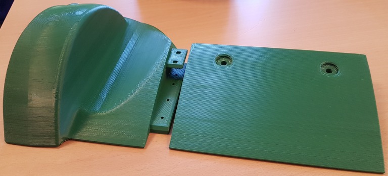
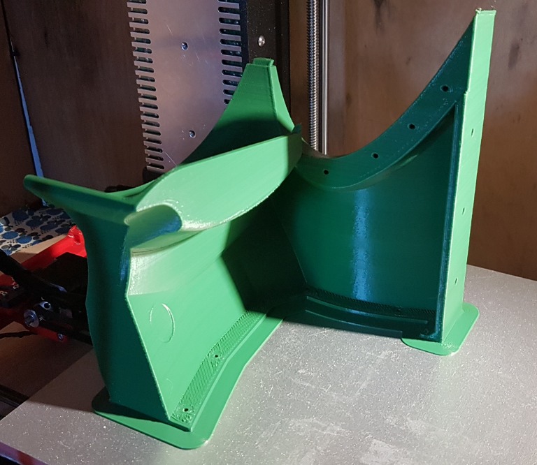
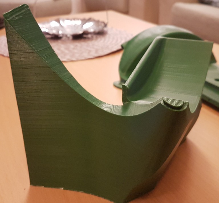
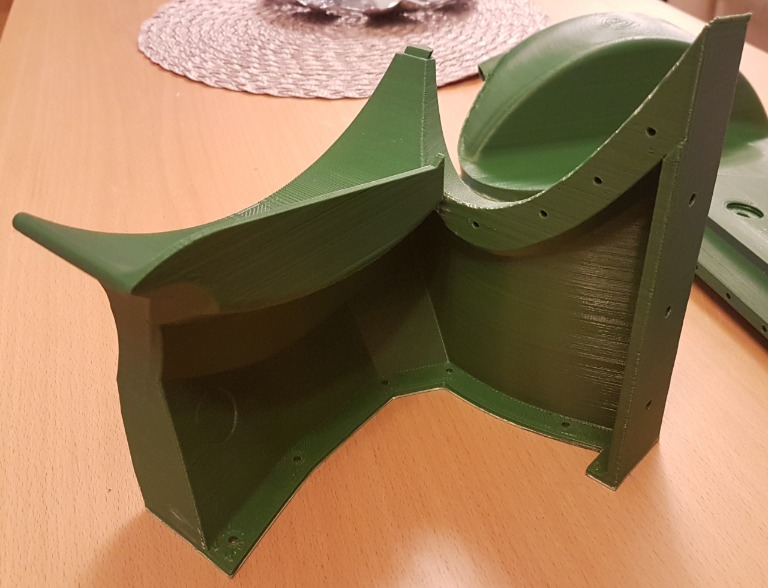
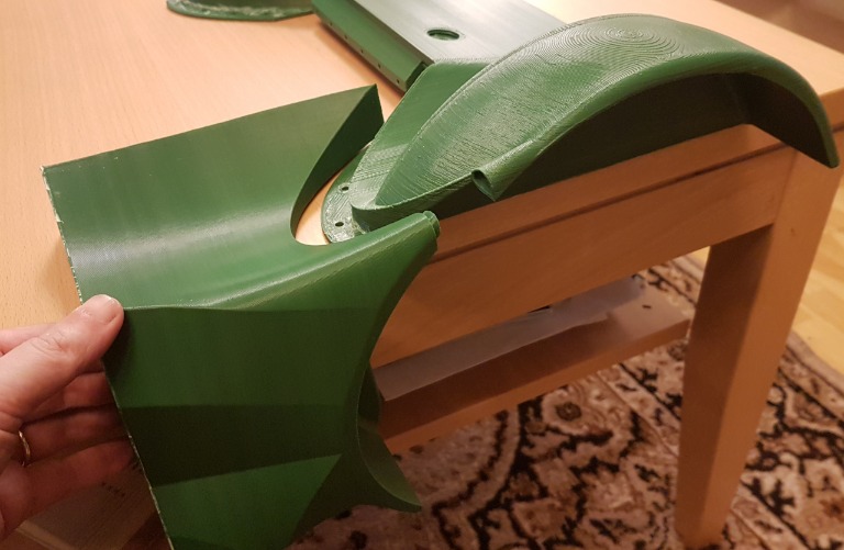
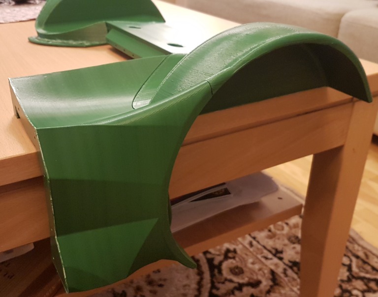
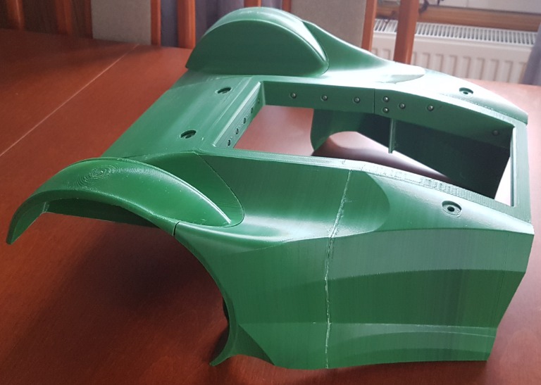
Cut cover almost ready
2019-02-2616.07.44.jpg

2019-02-2616.09.38.jpg

2019-02-2616.09.50.jpg
 
I can't edit first post?

Filament is Devil Design ASA, 18,50€/kg, and my printer is slightly modified prusa mk2s. Building space is 230x250x205 and modified parts are made to fit that.
I'm using e3d Volcano hotend with 0.6 nozzle, so printing times are reasonable. It can push plastic at least 30 mm^3/s
Printing ASA is similar than ABS printing. It warps easily and printer has to be in enclosure.
For rear wheels I'm using devil design's TPU also but I dont have that yet.
2019-02-2617.54.17.jpg

2019-02-2613.10.30.jpg

Attachment: https://forum.ardumower.de/data/media/kunena/attachments/4741/2019-02-2617.54.17.jpg/
 
Zuletzt bearbeitet von einem Moderator:
Hi,

thanks for sharing your improvements too. Your perimeter box looks good, did you check if it collids with front nose or may you be able to measure the clearance around?
Also, your wheelhouses looks good. They seems to be more robust than Robin or mine. Are they compatible with origin Arctic Hare design?

It would be great if you share your files too. I assume Thingiverse is the place to go with a remix of Robins project. This is the easiest way to keep all files up to date in my opinion.

Patrick
 
Good work, that looks really robust. I add this to my list for next iteration of my design.
 
jussip schrieb:
Question about BMS connection. I'm wondering C- port connection, do I put it parallel to P42 GND or charger GND only to BMS C-port? (no charger GND to P42)
This BMS cannot work right if -p and -c is connected together. So, if using this I have to leave charger gnd out of pcb. Does this cause any problems? Another option is to get new bms with no separate charging port.
 
Zuletzt bearbeitet von einem Moderator:
I ordered new BMS. This one has not separate ports so it will work for sure.

I have some problems when powering pcb up. Only way to get it on is use usb cable on due, when opwer is up I can remove usb cable and it stay on. P20 button does nothing, switch is ok and there is 4,2v other pin, other is ground. When powered up it beeps error, CPU speed error and RTC error. RTC battery is ok but time disappear when power is off. Motors, odometry and BT are only that works.

Just noticed that due gets really hot, barely can touch it.
 
Hi.
What about JP8 (check if contact is OK).
DC/DC step down output voltage ?? and small SMD fuse solder ?
Led on the Board ?
The Power is manage by the output 4 of the Due (check solder).
If the I2C bus is not powered by the 24V Battery voltage the error is possible.
Certainly the Due is hot because it power all the Module.

By.
 
JP8 is ok. DC/DC output is set to 9v but there is no voltage input nor output side before I wake up whole system via usb cable. Fuses are all ok. No leds lit on board before powering up, only charger/station led if it is connected. When powered up +24v, BT leds lit and buzzer led blinking.
 
Jp8 need to be always on and not auto for testing.
Maybe this test can help for jp8 auto position
To be sure you can put a simple code inside the due with output 4 always on
So without usb power, power the 24v on the board and start it with the p20 button .
What kind of power supply did you use ?
By.
 
Code:
t   126 L  1 m0 ERR  rpm    0    0 set    0    0 sen    0    0    0 bum    0    0 dro    0    0 son   0 yaw   0 pit   0 rol   0 bat 21.6 chg  0.8  0.0 imu  0 adc  1 LawnMower
ERR_RTC_DATA
ERR_BATTERY
Battery warning: triggered batSwitchOffIfBelow 21.65<21.70
loadSaveErrorCounters: write
loadSaveErrorCounters addrstop=423
loadSaveRobotStats: write
loadSaveRobotStats addrstop=826
BATTERY switching OFF
buttonPressed
SEN_BUTTON
BATTERY switching ON again


Voltage on battery is 24,95 on multimeter, not that 21.65. Button not pressed because it wont do anything. pcb is always on mode.
Output 4 always on keep power up and constant buzzer beep.

Battery 7s3p 18650 li-ion and charger is marotronics 1,5A.
 
I suppose here you have acces to arduremote or pfod.
In the code you have set the correct Pcb 1.3.
So first Please change the switch off if below in setting battery and set it to 20V to avoid the err bat.(Voltage error can be check later)
Now you need to check the i2c bus for the Rtc .there are a lot of post on forum for this but try this.
In setting set the use timer to on.
Do not set any timer.
Set the date and time correctly.
Use Save setting. It make take more than 5 sec if the i2c and rtc eprom are ok.
Restart all and check is the rtc error is always here.
 
I have working pfod connection. I did what you suggest. RTC error is still present, setted time disappear when reboot due/pcb.
Pcb wont start without waking with due usb cable. (JP8 always on) I assume that pcb should be powered off via pfod-commands-OFF, it wont do that.
 
I suppose you use github azurit version.
Take a look in the code and test section , hou have a rtc.ino code ,test it.

Without usb cable you need the p20 button to start the pcb and the pcb need to stay always on if jp8 is set to on.
To stop the pcb use the main switch to disconnect the battery.
The jp8 auto position is used to protect the battery on low voltage but in this version no pfod power off command.
 
Oben