Arctic Hare mod by Jussi

In fact i don't have a big knowledge in HASSIO and i use this in the main configuration.yaml.

Anhang anzeigen 2248

But maybe a simple folder named packages with the s avoid adding this line ??
Look at official version
I have errors and i wine able to restart. This autocheck is quite new function last release o think conif you have older version maybe this without s is ok.
I will be back home in two days so i will check this "name problem"
Do you use pull-up on gy88?
 
yaml code is an example only, feel free to change it for your needs
directory can be named whatever you like :) you need to create that directory also, I named it simply 'packages' but that directory have to define in configuration.yaml
YAML:
homeassistant:
  packages: !include_dir_named whatever

do I need a code change when changing the Bluetooth module to esp32. (cant' get it to work)
 
  • Like
Reaktionen: szu
do I need a code change when changing the Bluetooth module to esp32. (cant' get it to work)
For AZURIT or AZURITBER there is no change in the ardumower code if you want to use ESP32 connected on PCB1.3 BT connector
You can see the WIRING into Azuritber RFID option (simply do not connect the reader).

BUT :
You need to load a simple BT passerelle into ESP32.
You can do that using arduino IDE ,but don't forget to push the boot button when download start.
Code is in my Git.
bt pass.png
 
ok, the old esp32 got wet last summer and I now replaced it. Must be something else broken also, I can connect esp32 but pfod app don't show up
I was hoping that some code change is needed, now I have to find fault :D
 
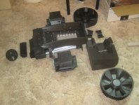
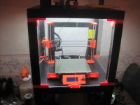
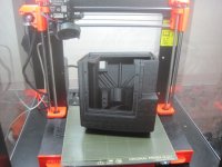
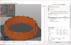
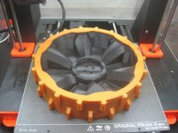
I am building a replication of this build. It is going reasonably well so far, given my inexperience in 3D printing. I am using a Prusa i3 MK3S+, basically factory stock with no modifications. I have been printing parts using Prusament ASA in black with relatively good success. I wasn't experienced with higher temperature printing, but I am learning rapidly! I built the IKEA Lack printer enclosure from the instructions on the Prusa website, it is necessary to obtain good results with the warp-prone ASA plastic. I have only had a couple of print problems so far, on the very large/tall parts such as the rear motor housing, which failed about 18 hours into a 24 hour print due to heat creep and an extruder jam. Thankfully only the top few millimeters of the print were messed up, I was able to cut it off flush using a table saw and use the slicer software to print a replacement part for the remainder that didn't print right. I haven't glued the pieces together yet, perhaps they will work if I can get the alignment close enough. Otherwise, it will have to be reprinted and a lot of plastic wasted. As the print grows during the build process, I realized that the temperature is higher near the top of the enclosure than the bottom, which is why it only failed as the part got tall. I am replacing the heat break with the upgraded titanium part from E3D so hopefully I can avoid this problem in the future. I am using the PrusaSlicer default settings for Prusa ASA, 260C nozzle and 105C/110C heatbed temperature (first layer/other layers). All the smaller parts printed with no problems, good layer adhesion and good bed adhesion using the PEI smooth steel sheet with no additional preparation. Adhesion on to the print bed is almost too good and parts are moderately difficult to remove.

I have been using the stock 0.4mm nozzle for printing, with layer height 0.3mm and extrusion width 0.5mm, this gives print times close to what can be obtained with the larger 0.6mm nozzle. Also I don't have the upgraded volcano hotend, which would further reduce print times. I may have to go this route as I start printing the body pieces, I wanted to see how far I can get with the stock configuration before it gets too impractical.

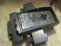
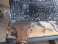
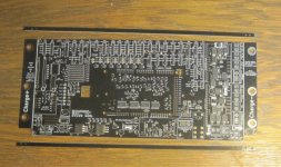
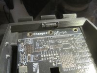
Waiting on my electronic parts to arrive, I have the mainboard and most of the other items on order and in the mail.

Other items of note: the aluminum extrusion is actually 20x20mm, not 25x25mm as labeled in the CAD model. If you measure the printed parts it's obvious that they are sized for 20x20mm extrusion. Also, since I am in the US, obtaining the metric size miscellaneous hardware is quite a bit harder and I can't just run down to my local hardware store. Also, the battery case seems too big for the 7S pack built using the NESE 3P modules. I printed them in clear PETG, and obtained the matching hardware from AMtech (3 weeks shipping from Lithuania!), and they fit but there is considerable extra room that doesn't appear in the pics from early in this thread. I don't have suitable lithium batteries on hand to complete the build, but I do have enough recycled laptop 18650 cells with usable capacity to be able to power up and test the electronics at least, before I invest in new cells to run the motors.
 

Anhänge

  • IMG_2178_small.JPG
    IMG_2178_small.JPG
    139,7 KB · Aufrufe: 33
  • IMG_2179_small.JPG
    IMG_2179_small.JPG
    147,7 KB · Aufrufe: 29
Some progress, and some setbacks. First, I was able to successfully print the large rear motor housings, with no more heat creep issues. I now have the titanium heat break installed, and a 0.6mm nozzle, and I also reduced hotend temperature to 255C (from 260C) and heatbed temperature to 105C (from 110C) in the slicer settings, to reduce the chances of heat creep problems. Using the default extrusion width for 0.6mm nozzle in PrusaSlicer, and reducing the speeds slightly to keep the volumetric flow rates at no more than 11 mm^3/s, gives a print time of 17h3m for this part.

Second, the setback is that apparently the 1.4 version mainboard doesn't quite fit in the space for it in Jussi's design. I now realize, after looking closely at the pictures, that of course the design was made around the 1.3 version mainboard, which is what was available at the time. The difference in dimensions isn't large, but it is enough to prevent the board from sliding into its place. I'm not sure what the best direction to proceed is. I can try to design a small shim piece to fit between the front and rear pcb box halves, but then this will cause a host of other alignment issues. Better would be to actually redesign everything to account for the revised size of the PCB, but of course without access to the original CAD files this would be difficult if not impossible (certainly for someone of my limited CAD skills). Jussi, any chance you're still hanging around here?
 

Anhänge

  • IMG_2180_small.JPG
    IMG_2180_small.JPG
    160,5 KB · Aufrufe: 29
  • IMG_2181_small.JPG
    IMG_2181_small.JPG
    221,3 KB · Aufrufe: 30
I finally made some progress on this impasse I had reached. It turns out, on closer inspection, that along the top and bottom of the PC board, some of the marking lines are actually SCORE LINES and a few millimeters of the board can be cleanly snapped off without harming anything. I did this using a bench vice and it worked great, solving the width problem. The length problem required just a bit of Dremel surgery on the plastic chassis piece that interferes with seating the board properly. A few minutes later and I had it solved. It's still quite a tight fit and you have to flex the board slightly to get it in or out, but it does in fact fit.
 

Anhänge

  • IMG_2188_small.JPG
    IMG_2188_small.JPG
    202,1 KB · Aufrufe: 26
  • IMG_2189_small.JPG
    IMG_2189_small.JPG
    140,4 KB · Aufrufe: 25
  • IMG_2191_small.JPG
    IMG_2191_small.JPG
    211,1 KB · Aufrufe: 26
Hi sustainablestew, congrats for the solution you found for the integration of the 1.4 PCB. I'm living in France and as for you, it's quiet hard to find all informations about the material needed to build one. Do you havea topic on this forum for your build ? I'd like to see what happens with it.
About the CAD files, the STL files from thingiverse should be useable with Fusion360 to be adjusted for the new PCB, but of course, man would do this for it's own machine, if it wouldn't fit correctly... .
Hoping to find news about your build.
 
LaurentS, no there isn't a separate topic on the forum for this build. I'm basically just attempting to replicate Jussi's remix of the original Arctic Hare Ardumower design. In addition to looking snazzy, it has some improvements over the stock Ardumower design, including dual mowing motors and a bigger battery, thus giving larger mowing area capability. I wish Jussi was still around to offer advice, but he doesn't seem to be active on the forums now. Perhaps he will return in the future. Now that I have overcome the PCB fit clearance problem, I have to solve a few other problems. One of these other problems is that Jussi made the design files to fit his personal 3D printer, which is a slightly modified Prusa, not factory stock like I have. Apparently he has something like the linear rail mod, which increases the Y-axis travel by about 1cm. The only pieces which require this full travel are the outside tires (real_wheel_surface.stl), so I have been working on this file to try to massage it into a form that's printable without expensive printer mods. First, I tried using PrusaSlicer to reduce the Y-axis scaling to 96% while increasing the X-axis scaling to 104%. This will keep the perimeter essentially the same but will turn the circle into an ellipse, requiring a bit of distortion to fit the tire onto the wheel rim. With only 4% difference, I thought this might work, and it ALMOST does, but not quite. The fit on the tire is not good enough, the little inner ribs are also scaled out of proportion so they no longer quite match up. I was finally able to achieve a workable solution by scaling both the X and Y axis to 96%, and then using the modifier feature of the slicer software to subtract the unscaled shape of the wheel from the resulting (slightly smaller) tire. This gives a thinner wall thickness and slightly smaller diameter than the original tire, but it does fit on the rim. As a bonus, it also uses less of the TPU plastic to print. To print the tire, I used the moderately priced Hatchbox TPU in an orange color (see photos). I also have the .3MF file exported from PrusaSlicer with all the settings I used, but apparently the forum software won't allow uploading of other file types like .3MF, I guess if anyone needs this file they will have to message me through the forum and I can email it.
 

Anhänge

  • rear_wheel_surface.png
    rear_wheel_surface.png
    383,8 KB · Aufrufe: 27
  • IMG_2192_small.JPG
    IMG_2192_small.JPG
    193,9 KB · Aufrufe: 30
  • IMG_2193_small.JPG
    IMG_2193_small.JPG
    180 KB · Aufrufe: 29
Thanks for your answer ! I noted your really interesting solutions ! I've never printed TPU on my Artillery Hornet, but I will try, nice orange TPU ! you could add your files on Thingiverse.
 
Oben