//PID controller: track perimeter
void Robot::motorControlPerimeter() {

//3 states
//wire is lost
//On the wire staright line pid fast action
//Back slowly to the wire pid soft action


//Control the perimeter motor only each 30ms
  if (millis() < nextTimeMotorPerimeterControl) return;
  nextTimeMotorPerimeterControl = millis() + 30; //possible 15ms with the DUE
  //tell to the pid where is the mower   (Pid.x)
  perimeterPID.x = 5 * (double(perimeterMag) / perimeterMagMaxValue);
  //tell to the Pid where to go (Pid.w)
  if (perimeterInside) {
  perimeterPID.w = -0.5;
  }
  else {
    perimeterPID.w = 0.5;
  }
  //parameter the PID
  perimeterPID.y_min = -motorSpeedMaxPwm ;
  perimeterPID.y_max = motorSpeedMaxPwm ;
  perimeterPID.max_output = motorSpeedMaxPwm ;
//and compute
  perimeterPID.compute();


//First state wire is lost
//important to understand TrackingPerimeterTransitionTimeOut It's if during this maximum duration the robot does not make a transition in and  out then it is supposed to have lost the wire, the PID is stopped to go into blocking mode of one of the two wheels.
// If the trackingPerimeterTransitionTimeOut is too large the robot goes too far out of the wire and goes round in a circle outside the wire without finding it


// If the second condition is true the robot has lost the wire since more trackingPerimeterTransitionTimeOut (2500ms) for example it is then necessary to stop one of the 2 wheels to make a half turn and find again the wire
  if ((millis() > stateStartTime + 10000) && (millis() > perimeterLastTransitionTime + trackingPerimeterTransitionTimeOut)) {

	//If this condition is true one of the 2 wheels makes backward the other continues with the result of the PID (not advised)
	if (trackingBlockInnerWheelWhilePerimeterStruggling == 0) { //
      if (perimeterInside) {
        rightSpeedperi = max(-MaxSpeedperiPwm, min(MaxSpeedperiPwm, MaxSpeedperiPwm / 2  + perimeterPID.y));
        leftSpeedperi = -MaxSpeedperiPwm / 2;
      }
      else {
        rightSpeedperi = -MaxSpeedperiPwm / 2;
        leftSpeedperi = max(-MaxSpeedperiPwm, min(MaxSpeedperiPwm, MaxSpeedperiPwm / 2 - perimeterPID.y));
      }
    }
	//If this condition is true one of the 2 wheels stop rotate the other continues with the result of the PID (advised)
    if (trackingBlockInnerWheelWhilePerimeterStruggling == 1) {
      if (perimeterInside) {
        rightSpeedperi = max(-MaxSpeedperiPwm, min(MaxSpeedperiPwm, MaxSpeedperiPwm / 2  + perimeterPID.y));
        leftSpeedperi = 0;
      }
      else {
        rightSpeedperi = 0;
        leftSpeedperi = max(-MaxSpeedperiPwm, min(MaxSpeedperiPwm, MaxSpeedperiPwm / 2 - perimeterPID.y));
      }
    }

	//send to motor
    setMotorPWM( leftSpeedperi, rightSpeedperi, false);
    // we record The time at which the last wire loss occurred
    lastTimeForgetWire = millis();
// if we have lost the wire from too long time (the robot is running in a circle outside the wire we stop everything)
    if (millis() > perimeterLastTransitionTime + trackingErrorTimeOut) {
      Console.println("Error: tracking error");
      addErrorCounter(ERR_TRACKING);
      //setNextState(STATE_ERROR,0);
      setNextState(STATE_PERI_FIND, 0);
    }
	// out of the fonction until the next loop
    return;
  }


 // here we have just found again the wire we need a slow return to let the pid temp react by decreasing its action (perimeterPID.y / 2)
  if ((millis() - lastTimeForgetWire ) < trackingPerimeterTransitionTimeOut / 1.5 ) {
    rightSpeedperi = max(0, min(MaxSpeedperiPwm, MaxSpeedperiPwm / 2 +  perimeterPID.y / 2));
    leftSpeedperi = max(0, min(MaxSpeedperiPwm, MaxSpeedperiPwm / 2 -  perimeterPID.y / 2));
 }
  else
//we are in straight line the pid is total and not/2
  {
    rightSpeedperi = max(0, min(MaxSpeedperiPwm, MaxSpeedperiPwm/1.5   + perimeterPID.y));
    leftSpeedperi = max(0, min(MaxSpeedperiPwm, MaxSpeedperiPwm/1.5  - perimeterPID.y));

  }

  setMotorPWM( leftSpeedperi, rightSpeedperi, false);


  //if the mower move in perfect straight line the transition between in and out is longuer so you need to reset the perimeterLastTransitionTime

if (abs(perimeterMag ) < perimeterMagMaxValue/4) {
    perimeterLastTransitionTime = millis(); //initialise perimeterLastTransitionTime in perfect sthraith line
  }


}

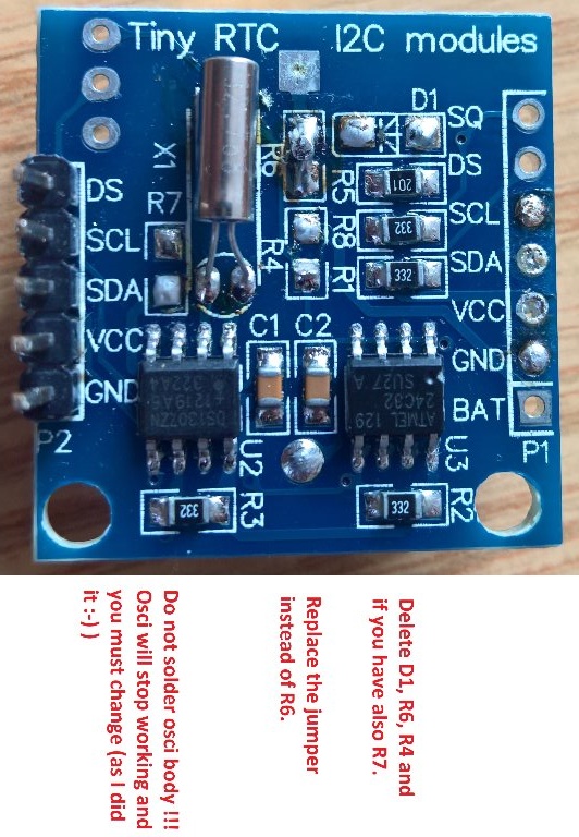
") so I want start mowing asap.
so I want start mowing asap.