Alex's ardumower - My DIY ardumower modification

alda

Member
Hi,

Let me show you my mower project. Starting point is here running project, but I did some modifications. Hope that this thema will help share informations for beginners like I am.

First version which I made :

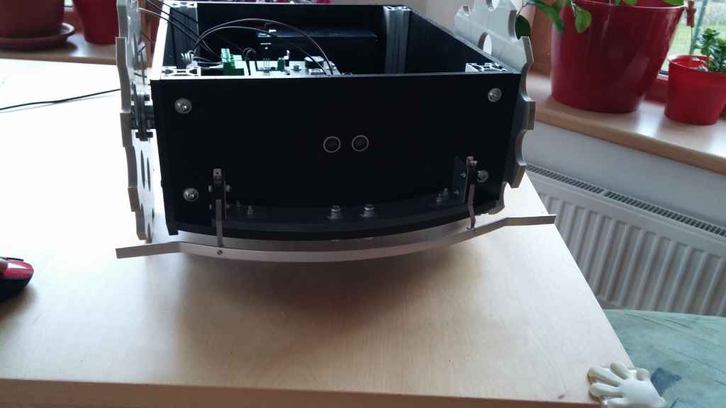
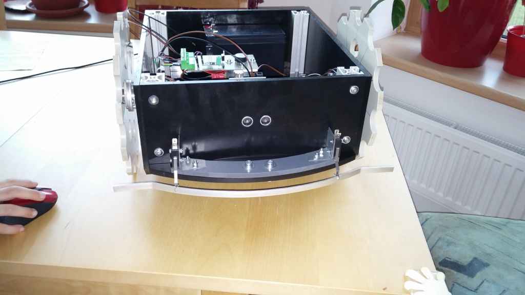
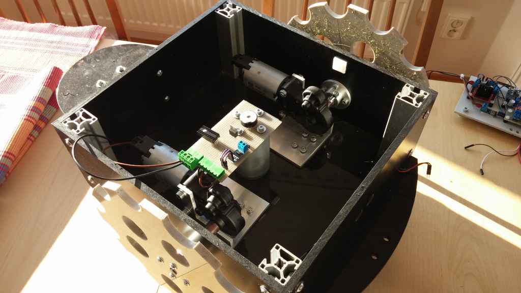
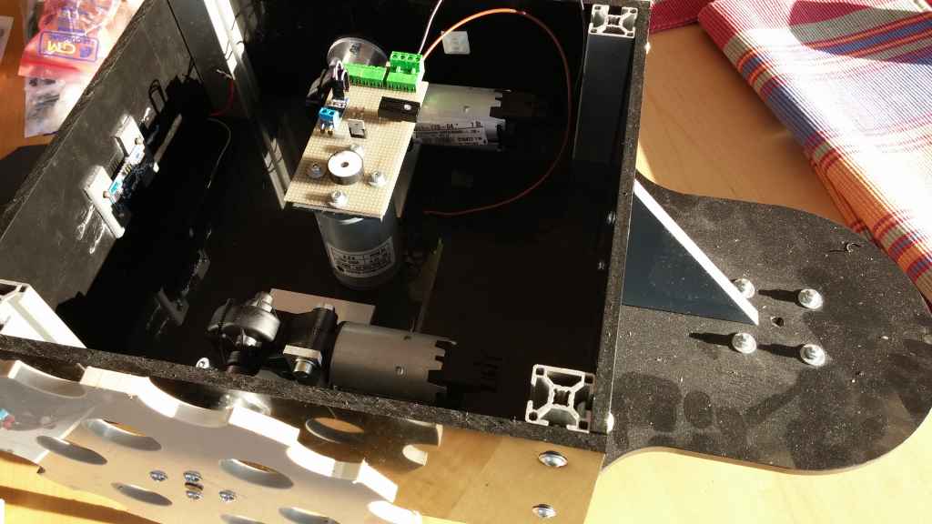
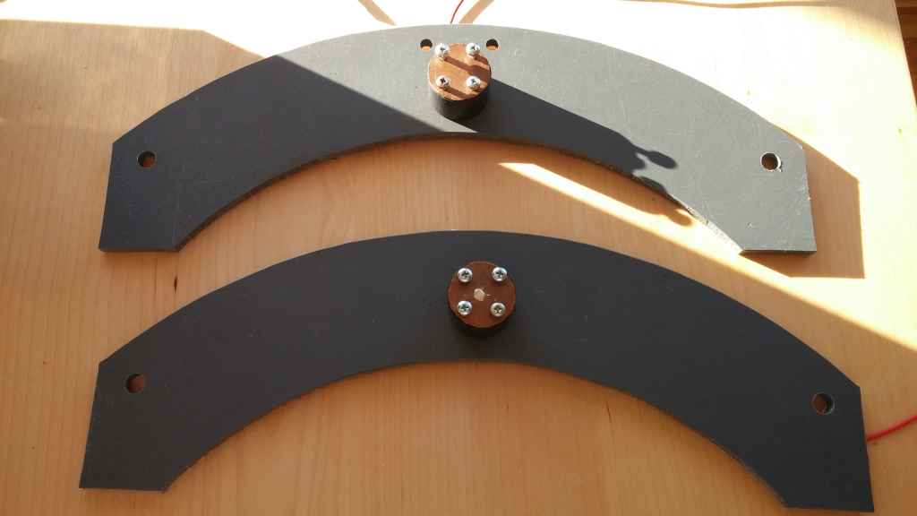
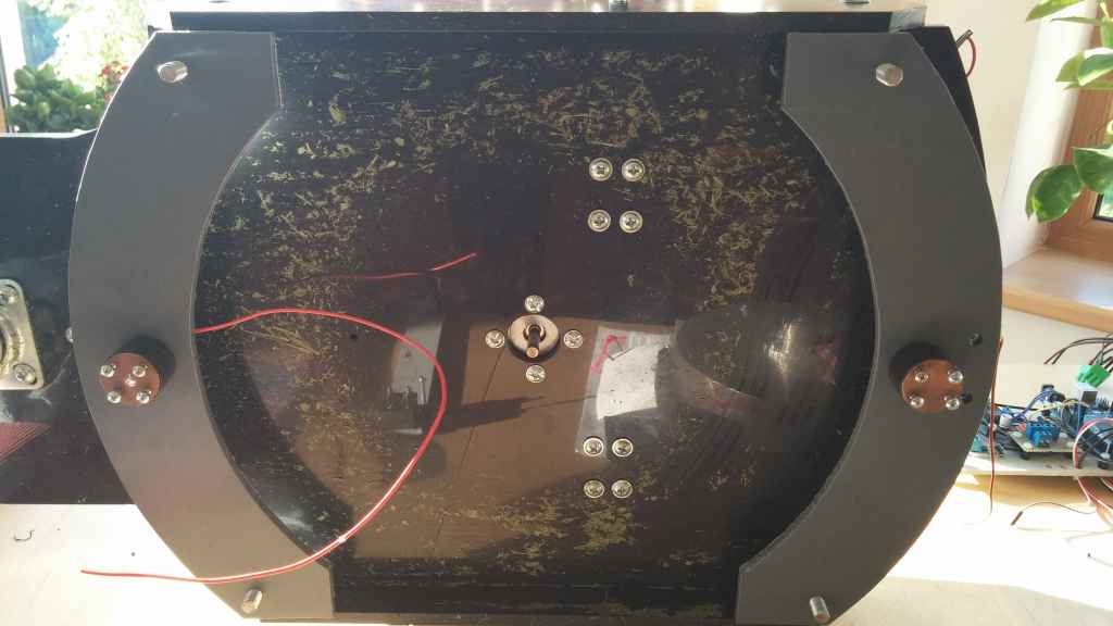
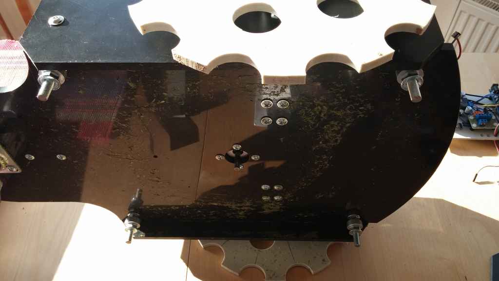
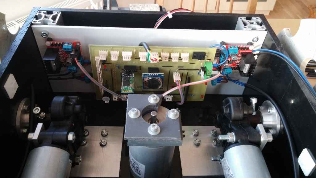
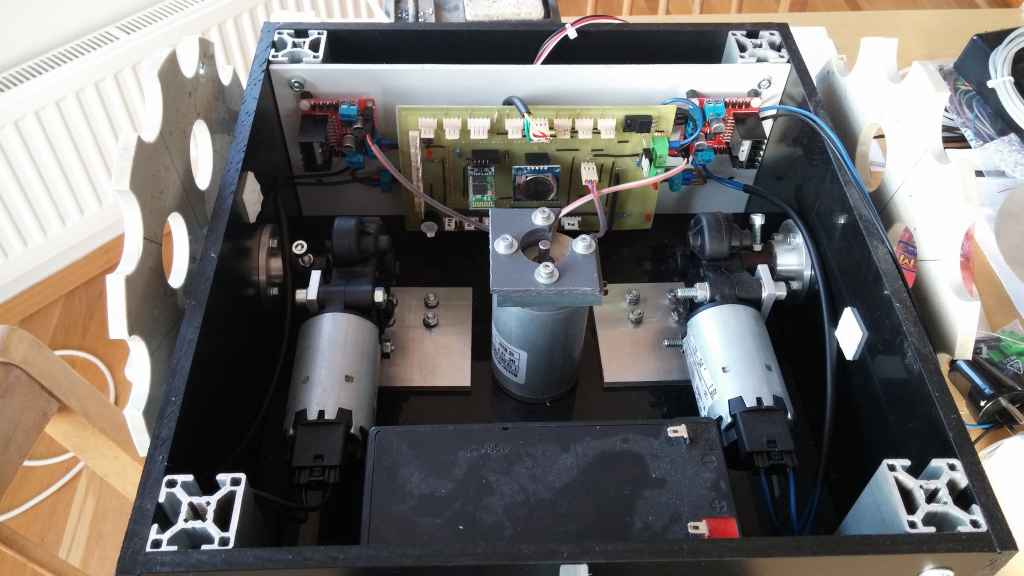
Finished was chassis - my modification is, that back wheel is part of bottom desk and not upper
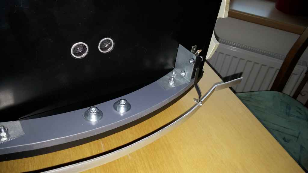
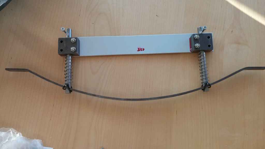
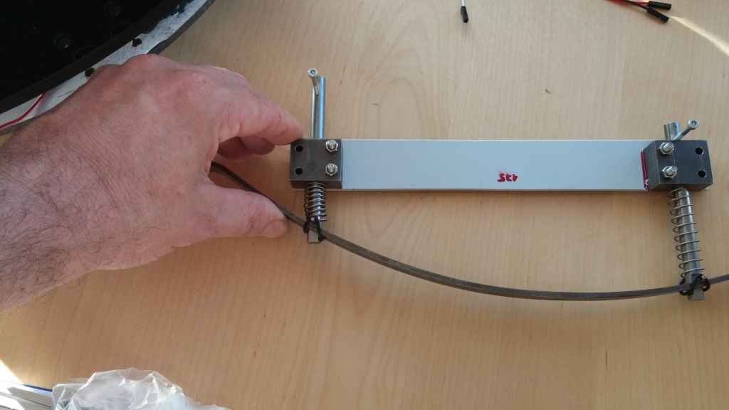
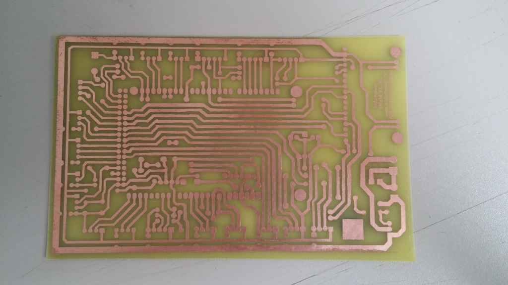
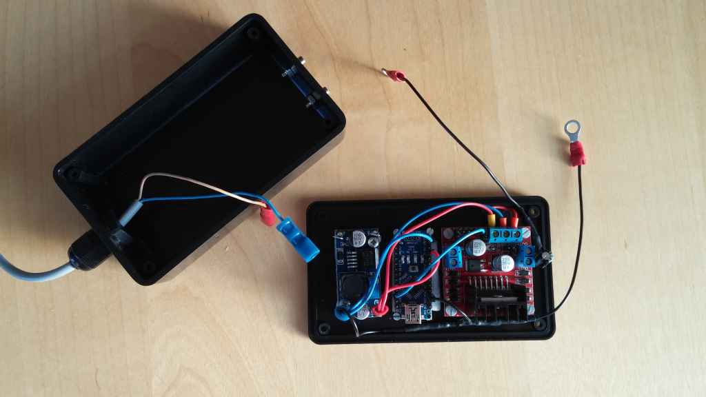
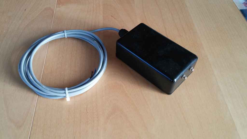
Front bumper was in development together with perimenter sender/receiver and lawn sensor.

20140406_191401_2014-06-27.jpg


20140406_191416_2014-06-27.jpg


20140406_191424_2014-06-27.jpg


Alex
 
Because there was problems with wheel motors which I had, I switched to pollin motors and I also changed cutting motor. Also bumper was reworked. Current status ( main electronic board is removed ) :


20140627_063811.jpg


20140627_063854.jpg


Last version of the front bumper ( now mounted on the temporary plastic board ) :


20140627_064100.jpg


20140627_064114.jpg


Also lawn sensors are in development. My idea is that this sensors are part of underrun protection :


20140627_063935.jpg


20140627_064018.jpg

Attachment: https://forum.ardumower.de/data/media/kunena/attachments/1183/20140627_063811.jpg/
 
Zuletzt bearbeitet von einem Moderator:
My main open points :

Perimenter receiver - in development ( my plan is that receiver is part of the underrun protection ). Sender is done
Front bumper finish - mechanic is done, only microswitch implementation is necessary
Lawn sensors - done, but I must implement connectors into bottom desk and connect into mega.
Electronic board - implementation of the mega shield - in development - PCB is done :

20140627_080831.jpg


Chassis modification - I want test to cut out back side of the bottom desk where is small wheel and I wand connect small wheel with back side of the main box.

Cutting blade - now only basic version with rotary knives - need development.

Charging station - only basic idea


Alex
Attachment: https://forum.ardumower.de/data/media/kunena/attachments/1183/20140627_080831.jpg/
 
Zuletzt bearbeitet von einem Moderator:
Now picture of the arduino shield with values of the components :


20140703_131824.jpg


My modifications :

1.Diode for bad polarity isn't here, because for good function with fuse 20A must be this diode for very high current ( min.40A ) and this kind of diode is quite big.
2.Plan is use 2xSTL298N motor driver ( as in official schematic )
3.Plan is use LM2596 for 5V supply ( as in official schematic ) - so Traco TSR 1-245, C1, C2 and P15 are not fitted on board

Alex

Edit: How I produced this board :
I used pdf file from download section and printed out PCB layout to special film on the laser printer. The image of the film after heating from iron is transferred to the PCB. If some errors will occure, you can correct with alcohol fix. Then only etched, drill, we place components and Solder. Cost is very low and result very good.
Attachment: https://forum.ardumower.de/data/media/kunena/attachments/1183/20140703_131824.jpg/
 
Zuletzt bearbeitet von einem Moderator:
Congratulations Alex

As far as I know you have build the 2nd ardumower shield, Peter was the first one (ofcourse I was the reference =) )

Looking forward to get corrections etc on the board , but I dont think there are any

Walter
 
Hi Alex,

It all looks very good; very clean build :woohoo:

Did your initial bumper setup work well? It looked simple and robust...

What motors do you use?

Frederic
 
Frederic Goddeeris schrieb:
Hi Alex,

It all looks very good; very clean build :woohoo:

Did your initial bumper setup work well? It looked simple and robust...

What motors do you use?

Frederic


Hi Frederic,
Thank you.
Regarding motors - I am using motors from pollin.de ( GMPD / 404 980 - 1, 12V, 22rpm, 4Nm ) and for mower now I have motor from buehlermotor.com
Type is 1.13.044.235.03 ( 12V, 3000rpm ).
Regarding bumper - Now it's mounted on the mower, all looks OK,now I'm only looking for best micro switches positions and holders for it.
More pictures I will send later.

Alex
 
Zuletzt bearbeitet von einem Moderator:
So shield is installed and now I'm implementing sensors.
Current sensors for wheels are working, also ultrasound is ok.
I had a problem with current sensor for Mow motor and I found problem in SW :
Was necessary unmark first line ( case SEN_MOTOR_MOW .... ) :

switch (type) {
//case SEN_MOTOR_MOW: return( (int)(((double)analogRead(pinMotorMowSense)-motorMowSenseZero) * motorMowSenseScale) ); break;
// old wiring
//case SEN_PERIM_LEFT: return(((double)analogRead(pinPerimeterLeft))/4.0); break;


Alex
 
Hi Alex

for fixing magnet i use Pattex Stabilit Express.

Looks verry god. Were do you Place the 5V stepdown regulator ? Or is on the right upper side an 7405 ?

Stefan
 
PLEASE HELP

Still have a problem with Mow RPM. My opinion was, that neodyme magnet lost magnet field due to high temperature which I used during magnet fixation with shrink tube. Magnet wasn't strong enough, so I used a new one. Now I can measure on the hall sensor output 2,55V when neodyme magnet is out and 4,9V when magnet is near to hall. Same voltage I can measure also directly on the D51 on the arduino mega, but RPM is still = 0.

Any idea what can be a reason ??

Maybe it's a SW problem. So here is my code which I'm using :


ardumower.zip


Alex
Attachment: https://forum.ardumower.de/data/media/kunena/attachments/1183/ardumower.zip/
 
Zuletzt bearbeitet von einem Moderator:
Is 2.55V low enough to detect Signal as LOW ? I dont think so ... pull it to GND, so that it reaches nearly 0V when magnet is out.
 
Is there any schematic how to connect?

Maybe magnet orientation is bad and voltage signal must go down when magnet is near to sensor.
 
Oben