Valify - my robot lawnmower project

Hi,

your progress looks great. How do you plan to get your parts rain proof? There seems to be no kind of seal between your parts. I'm not sure if this will become a problem because the parts are compressed together by screws and I assume you won't take the robot with you when diving.
 
Hi Paddy, Thanks. I will use sealing paper and if needed after seal test I Will also but some tiny silicon o between the joints. Anyways This is the first prototype and Guess I will learn a bit on the way for next print. :)
 
As long as Printer is working, I'm continuing to work on the design of the new drive system.
All part is new on the way so lets have the first concept of the drive system ready when they arrive.
The reasons I have design it like this is because I want be able to change pulleys. The motor can be adjusted making it easier to adjust the CC from Small to big pulley. Also I able to easy adjust the belt tension.


This is my progress so far:
123.jpg


I hate messy cables and I was lucky that I can use 3/4 slots in each support beam to pull cables through the robot cross body. Happy!
IMG_2112.jpg

Attachment: https://forum.ardumower.de/data/media/kunena/attachments/4372/123.jpg/
 
Zuletzt bearbeitet von einem Moderator:
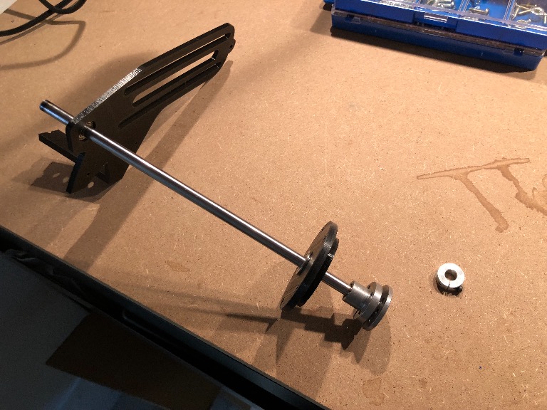
The pulleys are fixed with screw fit to a silver steel axle. The pulleys are bought from amazon.com https://www.amazon.com/gp/product/B00FGYMFS0/ref=oh_aui_detailpage_o00_s00?ie=UTF8&psc=1
 
Here is a nice video from the CNC milling of the first part.
[video]https://www.youtube.com/watch?v=N8MIpB3ZfS8&t=162s[/video]
 
Shafts are now ready. Splitting the shaft from 500mm to two 240mm. Grind top and bottom and bearings fits like a glove.
IMG_2330.jpg


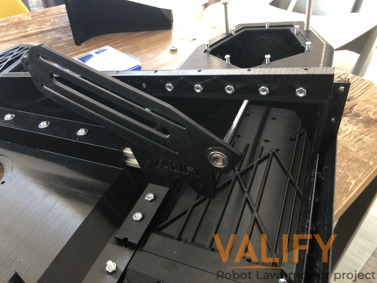
Test assembly with 3D printed motor brackets and wheel hub. Everything fits perfect! I will add some extra mountings for the the vertical support beam. Other then that I think they are ready for CNC milling.
IMG_2325.jpg


The horizontal support beam fresh from the CNC.
IMG_2331.JPG


Check out posts on the the build blog http://valify.se/2018/03/16/3d-printing-prototype-motor-brackets/ Attachment: https://forum.ardumower.de/data/media/kunena/attachments/4372/IMG_2330.jpg/
 
Zuletzt bearbeitet von einem Moderator:
I saw for the motor: No-Load Current: 1.9A
Means that, that the motor needs 1.9A running with no load and with load more?
This sounds a lot. Really intersting what the motor then needs with load later.
 
Yes. I was testing BLDC tool yesterday and the No-Load current was at ~0.3A. But I need to do the wires better with bullets connectors. Let me get back to you with the numbers when I have fixed the cables. ;)
 
Oben