Unable to communicate with esp32 module

ama

New member
I'm on the 1.4 board, esp32 for wifi and bte.

I have successfully installed the esp32 software and am able to telnet into the esp module. It doesn't want to speak to the main ardumower software though.

Listening in from the adafruit side, with the rest of the mower unpowered I get serial log such as this:
trying to detect Bluetooth 4.0 / BLE module (make sure your phone is NOT connected) 9600 ...
BLE: AT
trying to detect Bluetooth 4.0 / BLE module (make sure your phone is NOT connected) 115200 ...
BLE: AT
error: no BLE module found!

With the mower powered instead it looks more like this:

trying to detect Bluetooth 4.0 / BLE module (make sure your phone is NOT connected) 9600 ...
BLE: AT
Trying to detect Bluetooth 4.0 / BLE module (make sure your phone is NOT connected) 115200 ...
BLE: AT
? ⸮? ܶ? ⸮? ⸮⸮ ?? @ ⸮ ?? @? JQ "?? ⸮error: no BLE module found!

To me, this indicates that something is actually trying answering on the wire but the ardumower not making any sense of it.

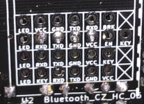
JP4 and JP10 are set as per the documentation. Wires between the bluetooth pins and the esp32 pins are also as per documentation as far as I can make out.

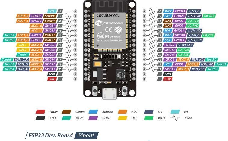
I'm at a bit of a loss here. Is this even the codepath which is responsible for adafruit-esp communication or am I staring at the wrong things? I'm I right to think that the esp32 (even for wifi) is emulating a bluetooth device to the sunray software which just treats everything on the other side of that wire as bte?
 
Did all LEDs turn on on the mainboard? And make the mainboard beeps? If not, on which I2C place did you install the temperature sensor? And on which voltage did you set the jumper for the temperature sensor, 3,3V or 5V? I have made the mistake, that I have connect the temperature sensor on the false I2C place and the mainboard did not boot complete and make a beep.
 
Did all LEDs turn on on the mainboard? And make the mainboard beeps? If not, on which I2C place did you install the temperature sensor? And on which voltage did you set the jumper for the temperature sensor, 3,3V or 5V? I have made the mistake, that I have connect the temperature sensor on the false I2C place and the mainboard did not boot complete and make a beep.
All the voltage LEDs turn on and the mainboard beeps once on startup if I start the mower up without being connected to it over usb. (I have yet to quite figure out what order of powering the mower board, the adafruit and the esp actually give what results. When the mower is left to boot undisturbed I can't get complete logs from the bootup procedure.)

I have not installed the temperature sensor (which seems to be the same as the humidity sensor?). I'm trying to get it running with a minimum of components plugged in first. Is that a bad approach? Does it expect/require some of the peripherals to be connected beyond the clock module (which is described as necessary in the documentation)
 
Where did you connect the ESP32? Clockmodul should be installed. And yes the temerature sensor is the huidity sensor.

Did you have connect the USB directly to the ESP32 and have you open the serial monitor of Ardunio tool? But do not forget to change the settings for the ESP32 board and the COM port. And set in the serial monitor the baud rate to 11200. Can you see that the ESP32 board did make a connection to your W-LAN? And I mean that you can also find the board by Bluetootht.
 
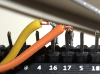
ESP32 connected here using 4 of the pins in the row that is 7 wide. The clock module is above it in the image if I'm not mistaken.

When connecting USB directly to the ESP32 (for installing the software and also for serial monitor) I could see that it booted up fine, connected but I couldn't get it to make the UART connection to the ardumower (if I understood what it was trying to do correctly). The ESP32 successfully connected to wifi and I was able to connect to it through telnet over the wifi. I have not managed to (but not also tried very much) to connect to the ESP32 using bluetooth.


1628359777657.png
 
After some more digging:
The bluetooth connection is UART so as long as it boots up (it does), the i2c bus should not be involved in further problems.
To eliminate crosstalk I switched to a shorter (and braided) cable. It does not seem to help.
But I did notice something else that is potentially a vital clue. On the esp32 side, stuff coming in over the wire seems to end in the AT that is expected. It is almost as if the buffers are full of junk waiting to be sent, to which the AT is appended. I then found the out-commented //BLE.flush(); on the adafruit side just before the message is sent, but enabling it did no good things.
 
Only the first message per "uart session" seems to suffer this problem. If I send a nonsense message first to clear the pipes, the following messages go through in the clear
String res = exec("CLEAR\r\n", false); //flush with garbage
res = exec("WHAT ABOUT\r\n", false);
res = exec("MANY MESSAGES\r\n", false);
res = exec("IN A ROW\r\n", false);
res = exec("ALL GOOD\r\n", false);
res = exec("AT\r\n", false);


[...] !⸮!f)%H⸮jM!? iJHQ+D⸮⸮⸮⸮CLEAR
760203 ping
760398 UART rx:WHAT ABOUT
761098 UART rx:MANY MESSAGES
761797 UART rx:IN A ROW
762204 ping
764205 ping
764292 UART rx:ALL GOOD
764993 UART rx:AT
764994 UART tx:OK
764994 UART rx:

I still need to get data sent back from the esp32 figured out somehow, but this might serve as a workable workaround.
 
Absolutely no success getting data back so far. Tried the HM10 module just to make sure, but no luck. I'm starting to suspect that I might have broken some traces on the pcb something. I resoldered the solder joints for the bluetooth jumpers. What solder points will this signal pass through? Does anyone know what adafruit pins should connect to the RXD/TXD and with what electrical characteristics?
 
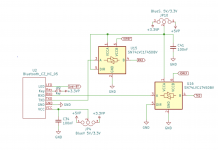
I had one of those good news/bad news situations today. I found https://github.com/Ardumower/ardumo...leitung/Ardumower Platine V1.4 Schaltplan.pdf and used it for tracing the signal path. U15 and U16 seem to be the interesting components here.

1628712098857.png

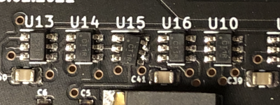
Let's just say that one of these is not like the other:

1628712188406.png

I will have to look closer at this in natural light tomorrow. My eyes are clearly not what they used to (or surface mounted components are just really, really small).
 
I very nearly managed to desolder it successfully (in order to solder it back in its correct orientation). Sadly, I managed to break one of the legs in the process. While I could theoretically repurpose one of the extra SN74LVC1T45 that I will not use (for a separate wifi module), I don't see why removal of another one would prove any more successful. Until I manage to get my hands on a new SN74LVC1T45 (or a new board that has its components on correctly), this mower is looking more and more like it will miss the entire mowing season of 2021.
 
I came up with a workaround. Since the wifi pathway is very similar and the ESP plays dual roles, I will not need to use the wifi circuitry for wifi. By instead plugging the ESP into the wifi connectors and a simple:

#define BLE Serial2
I managed to steer the robot around on my lawn with my phone. Time to get working on that GPS.

I hope this will not conflict with:

#define ROBOT Serial2

but so far things seem ok.
 
Hello Ama,

I also have the problem, that I can't get connection to the ESP32. The ESP itself is working perfectly, catches IP and shows as BLE device on Android. Still UART is not working at all.
Now if I understand you correctly, you plugged the ESP in P44 (WLAN). Correct? You configured Serial2 for this P44. Correct? Are you using Due or Grand Central?

Best regards,
Juergen
 
I've been playing around with M4 and ESP a lot now. I changed the UART pins on both back and forth. But still no communication. The problem is, that I did not know which UART port did not work, the one at the grand central M4 or the one at the ESP32. It was the one at the ESP32.
I bought a HM-10 BLE device. And immediately it showed up in the logfile.
So actually, I have BLE but no WiFi.
Still any hint about the config of the ESP32 is welcome.

Viele Grüße,
Jürgen
 
Hello Ama,

I also have the problem, that I can't get connection to the ESP32. The ESP itself is working perfectly, catches IP and shows as BLE device on Android. Still UART is not working at all.
Now if I understand you correctly, you plugged the ESP in P44 (WLAN). Correct? You configured Serial2 for this P44. Correct? Are you using Due or Grand Central?

Best regards,
Juergen
Yes, quite right. And I am using the Grand Central.
 
I've been playing around with M4 and ESP a lot now. I changed the UART pins on both back and forth. But still no communication. The problem is, that I did not know which UART port did not work, the one at the grand central M4 or the one at the ESP32. It was the one at the ESP32.
I bought a HM-10 BLE device. And immediately it showed up in the logfile.
So actually, I have BLE but no WiFi.
Still any hint about the config of the ESP32 is welcome.

Viele Grüße,
Jürgen
I'm clearly no expert on the ESP32, but doesn't it too have several programmable i/o pins? If so, it might be worth trying another pair.


1/3
9/10
16/17

all seem like workable alternatives (as do potentially most of the other i/o-pins).
 
Dear Ama,

thanks a lot for your help and information. Actually, today I am a little bit further: I know, that UART at ESP and at M4 are working. (I bought an HM-10 which worked immidiately)
When I check the communication on the CONSOLE of the ESP, you can see, that the ESP is not just receiving "AT" but something like "31102 UART rx:⸮ ⸮⸮⸮⸮⸮⸮⸮⸮⸮⸮⸮Ң⸮m⸮AT"
It always end with AT, what is would we would expect to see. The cmd variable in esp32_ble.ino has a lenght of 202 ytes (201 is "A", 202 is "T")
I still don't know, if this is sent by M4 or if ESP only means to receive it. Nevertheless, using BLE.flush() at line 75 in sunray.ino does not change anything.

Best regards,
Juergen
 
I had the same problem and got around it by sending a dummy message first and then my AT. I am sure there must be a better way of doing this but at least in my case that served as a workaround.
 
Dear Ama,

I can confirm your earlier post about cleaning the pipe:
If I send
String res = exec("Bloedsinn\r\n", false); res = exec("AT\r\n", false);
the AT command is recognised by the ESP and answered with OK.
I changed the question for version back from AT+VERR? to AT+VERSION. The second was not understood by the M-10.
This all leads to "Bluetooth 4.0/BLE module found!"

If the rest of the communication with ESP is working, I can't tell so far as actually the HM-10 is in the rover.
 
Oben