Robot Mower Communications Standard

Hallo, das "RMCS" ist m.E. bisher nirgendswo umgesetzt - bisher sind im Einsatz:

* pfodApp-Protokoll (Azurit Firmware): https://github.com/Ardumower/ardumower/blob/master/code/ardumower/pfod.cpp * ROBOTMSG-Protokoll (Sunray Firmware): https://github.com/Ardumower/Sunray/blob/master/sunray/robotmsg.cpp Das ROBOTMSG-Protokoll kann sich noch ändern (Sunray ist noch im Entwicklungsstadium). Es ist schlank gehalten und erlaubt die Steuerung des gesamten Roboters.
* Edison-Protokoll (Edison Firmware): https://github.com/kwrtz/Rolam/blob/master/Edison/ui.cpp
Gruss,
Alexander
 
Hallo zusammen,

gibt es an dieser Ecke schon was neues? Ich habe mich mit dem Control Center beschäftigt. Proof of concept steht und dank Node-Red hat man es schnell schön gestaltet. Problematisch stellt sich die bisherige Implementierung der serielle Kommunikation dar.

Konkret sieht es für mich so aus, dass der Raspberry im Mower steckt und sich per USB mit dem Arduino verbindet. Die serielle Ausgabe des Ardumower wird empfangen und durch Substring Operationen verarbeitet. Das klappt leidlich gut, schön ist es aber aus meiner sicht nicht. Die implementierten seriellen Kommandos arbeiten auch, sind aber für meine Zwecke nicht ausreichend. Die PFOD Kommandos kann ich nicht verwenden. Mir ist noch nicht klar, wie die Kommunikation über PFOd läuft. Ich dachte bisher, es sind einfach nur serielle Kommunikation über Bluetooth. Wenn ich die Pfod Kommandos in die serielle Konsole tippe, funktionert es aber nicht (werden nicht verstanden).

Bevor ich nun die bisherige Implementierung der consoleui.h ausweite um weitere Kommandos wollte ich mal bei euch nachhaken, wie ich es am besten implementiere. Was mir bisher fehlt sind vor allem:

- Fahrbefehle (am liebsten wäre mir ein Kommando, das die Geschwindigkeit und Richtung des Radmotors setzt, also etwa q+120-80, q (oder was auch immer noch frei ist) als Kommando, linker Motor PWM120 vorwärts, rechter Motor PWM 80 rückwärts). Damit könnte man eine Art Joystick auf der UI ausgeben und den Mower sehr gezielt steuern (besser als über PFOD). Meiner hat öfters Probleme beim einparken und geht auf Störung. Die bisherige manuelle Steuerung reicht nicht aus, um ihn einzuparken (zu ungenau).
- Sensorwerte in anderer Form als bisher, beispielsweise nur eine Info, wenn ein Wert getriggert wird.
- Auslesen der Konfiguration (welche Sensoren sind verbaut), um UI Elemente entsprechend ausblenden zu können (wenn kein Sonar verbaut ist, können die Sonar UI Elemente ausgeblendet werden)

Für Azurit stelle ich mir das so vor, dass man den RMCS über serielle Konsole implementiert. Um möglichst wenig im Code zu verändern, könnte man per Parameter zwischen bisherigen Output und RMCS umschalten. unsicher bin ich mir auch, ob das ganze viel Laufzeit frisst. Packt ein Mega das überhaupt noch? Kommendes Jahr wird es bei mir zwar ein DUE machen, aber wäre ja toll, wenn es auch auf dem Mega läuft.

Viele Grüße
Patrick
 
Hi Patrick.
To concern more people i think it's better to post in English.

Don't know exactly what you want to do with the Rasperry.

But actualy i begin to work on the comm between due and PI (for debug and mapping for the moment).
The PI is connected to the DUE with USB cable and use Native Serial USB on the DUE and it's work like a charm at 250000 bauds.
The comm protocol use NMEA sentence and the duration to send a simple 80 bytes message is near 7ms. so no problem for the DUE and GY88 IMU using his own DMP.Be very carrefull with GY801 because it's use to many ressource on arduino to have a correct result.

The arduino class to receive and decode message is made by me and based on UBLOX M8N code.
The PI python class is the Pynmea2 class you can find on the net.
It's only test and all is on the desk for the moment.

Maybe in the next weeks i can send you sample code.

By.
 
Hi Bernard,

as we discussed already on thread related to Control Center, I want to control my mower with a web ui. Something like the pfod app. It should be able to control the mower (at least manual control motors and setting states) and to display some measurements (sensor data, sensor trigger). I want to use a web UI because it looks way better and especially makes it possible to embed webcam stream.

I made some progress on control center and found it is a great way using node.js and node-red as ui.

The communication is done by serial (USB). Azurit already bring some serial commands, but they are not enough to control the robot like I want. So I'm wondering if it would be a good idea to replace the current serial communication (implemented in consoleui.h) of Azurit with something new. I think this will influence the Azurit code less. Simple add a new source code file and add some lines to be able to switch between consoleui and the new one. Because Console input and output is implemented by using classes, it should be easy to overwrite the class and use the same interfaces (methods)

At the end of game, Azurit will just send and receive different commands like today via serial console.

This is what I plan to do. What I'm asked for is how should the new communication protocol should look like? As I see, Alexander planned to do something similar (looking at WIKI RMCS). But when I look to sunray code, it seems he changed the protocol.

Alexander also wrotes about NMEA sentences but I'm not sure if he stick to it. In best case, my UI will work with less changes also with Sunray. This is only possible if we use the same message format.

As we have different targets on UI part, it seems we want to do the same on Arduino. So it would be best to share our ideas. It sounds you already implemented something for Azurit? Could you please share some examples of messages you use and how did you implement it?

Greetings
Patrick
 
Hi Paddy.
Here some screenshot of the starting of my work.
Screenshot_20180124-173603.png

The PI is connected to the Due by USB and the communication work in NMEA message.
Into the DUE
I create a new class named Rpiremote into AZURIT with:
void RpiRemote::writePi(String stringLine) to send a message
and
void RpiRemote::readPi() to read one.
and all the part to decode message and change the mower state based on PFOD command.


Code:
void RpiRemote::read_pfo()
{
  int counter = 0;
  char token[20];
  Tokeniser tok(buf, ',');
  while (tok.next(token, 3))
  {
    switch (counter)
    {
      case 1: //command as char
        {
          RpiCmd = token;
          if (RpiCmd == "ro") {
            // cmd: off
            robot->setNextState(STATE_OFF, 0);
          }
          if (RpiCmd == "rh") {
            // cmd: home
            robot->setNextState(STATE_PERI_FIND, 0);
          }


I use VNC to connect to the PI from my computer and run the python sketch.
If for example i hit the manual Stop button the PI send a NMEA message $RMPFO,ro,....
The Due receive it and understand that it's PFO (pfod command) type with ro inside the message so put the mower into the OFF state.
The Due send a non stop RMSTA (state) message and all the console message.

The code work actualy on the table but need a lot of time to create the user interface into the PI.

If you want i can send the code, but not very easy to understand.

By
Attachment: https://forum.ardumower.de/data/media/kunena/attachments/3545/Screenshot_20180124-173603.png/
 
Zuletzt bearbeitet von einem Moderator:
Hello Bernard,

Good work at your site. I startet something similar. I also use a separate class to communicate via NMEA like Messages. But I had to create my own protocol and was unable to use pfod commands. My solution looks more like the solution provided in wiki. It would be great if you share your DUE code.

Your GUI looks also cool, but as discussed earlier, Phyton is not the way I want to go. I want a responsive GUI working on every device with just a browser.

Nevertheless which GUI we use, we both use USB to communicate between DUE and PI, so I think it doesn't make sense to implement different ways for the same behavior. It is not important, which GUI sends or read messages unless they use all the same messages. What I'm missing in your screenshot is some status information like battery and charging information (voltage etc.) triggered events like bumper left triggered, sonar distance and so on. I'm not sure if it is better to extract these information from common console output (first try) or to implement some routines.

I startet implementing own routines related to wiki. For example, there is a status message containig battery level. Also you can set the push intervall of this message via separate command to set if status should be send every 100ms or only 1000ms.

Curently, my main focus is to create my second mower from scratch, so I stopped development here. But I will definetly continue when mower is operational.
I will create some screenshots and share my code here today or tomorrow so we can compare and maybe also commit to DUE implementation.

Patrick
 
Hello Bernhard and Patrick,
if I can support your development with hardware, please contact me. info@marotronics.de
Greetings Markus
 
Hello,

ok I checked everything again and pushed all parts together to give you a short view. It is an early development state but I think you can imagine what I'm doing.

First off, I want to show you some screenshots.

The first one shows the main page. As you see, it shows a live camera of my printer working. In real scenario, there will be an image of onboard camera. On the right, you see two diagrams showing current battery status and charging. We can make much more diagrans, line charts, histogram, cake what ever you want. Also we can set the heigth and width (everything node-red standard). The buttons you see (stop, Mow) will be replaced by a more fancy one (see below)

screenshot1.PNG


By pressing the hamburger menu on upper left, you can switch to other pages.
For example the serial monitor. I attach two pictures. The first one shows the common serial console. Pleae note that you can fully interact with the console like on PC.
screenshot2.PNG


You can select in mower code, if you want to use common serial console output (the normal one of Azurit) or if you want to use the new NMEA sentences of RMCS (robot mower communication standard, namend like the page on wiki). This is shown on next picture
serial-NMEA.PNG


Please note that the dashboard will only supprt the new communication standard. Otherwise, I must implement it two times. It is possible, but not the main focus so far.

The last screenshot shows a more fancy way to control the mower
manual_control.PNG


Thats all.

Now I want to show you what I've done in code.

First I added a few attributes to robot class to set some rmcs parameters (robot.h)

Code:
// ------------robot stats---------------------------
    boolean statsOverride ;
    boolean statsMowTimeTotalStart ;
    unsigned int statsMowTimeMinutesTripCounter ;
    unsigned long statsMowTimeMinutesTotal ;
    float statsMowTimeHoursTotal ;
    int statsMowTimeMinutesTrip ;
    unsigned long nextTimeRobotStats ;
[b]    // ------------robot mower communication standard---
	boolean rmcsUse;
	unsigned long RMCS_interval_state;
	unsigned long RMCS_interval_motor_current;
	unsigned long RMCS_interval_sonar;
	unsigned long RMCS_interval_bumper;
	unsigned long RMCS_interval_odometry;
	unsigned long RMCS_interval_perimeter;
	unsigned long nextTimeRMCSInfo;
  unsigned long rmcsInfoLastSendState;
  unsigned long rmcsInfoLastSendMotorCurrent;
  unsigned long rmcsInfoLastSendSonar;
  unsigned long rmcsInfoLastSendBumper;
  unsigned long rmcsInfoLastSendOdometry;
  unsigned long rmcsInfoLastSendPeri;[/b]


These changes in robot:loop (robot.cpp) ake care which kind of information to send

Code:
if (millis() >= nextTimePfodLoop){
    nextTimePfodLoop = millis() + 200;
    rc.run();        
  }
   [b]
  if (rmcsUse == true and millis() >= nextTimeRMCSInfo ) { 
	   nextTimeRMCSInfo = millis() + 100;
     rmcsPrintInfo(Console);
  }
	
  if (millis() >= nextTimeInfo) {        
    nextTimeInfo = millis() + 1000; 
	if (rmcsUse == false) { 
	  printInfo(Console);[/b] 
   
    printErrors();
    ledState = ~ledState;


also I had to change a few lines in mower.cpp

Code:
// ------ mower stats-------------------------------------------  
  statsOverride              = false;      // if set to true mower stats are overwritten - be careful
  statsMowTimeMinutesTotal   = 300;
  statsBatteryChargingCounterTotal  = 11;
  statsBatteryChargingCapacityTotal = 30000;
  
 [b] // ------------robot mower communication standard---
  rmcsUse					= true;   // if set robot mower communication standard (NMEA) is used.
  RMCS_interval_state	  	= 1000;
  RMCS_interval_motor_current = 1000;
  RMCS_interval_sonar 		= 1000;
  RMCS_interval_bumper		= 1000;
  RMCS_interval_odometry	= 1000;
  RMCS_interval_perimeter	= 1000;[/b]
  // -----------configuration end-------------------------------------


All the rest is implemented in a new file called rmcs.h (initially a copy of consoleui.h)

Code:
// robot mower communication standard

void Robot::rmcsPrintInfo(Stream &s){
  
  // Period since last send
  unsigned long now = millis();
  unsigned long durationSinceLastSendState = now - rmcsInfoLastSendState;
  unsigned long durationSinceLastSendMotorCurrent = now - rmcsInfoLastSendMotorCurrent;
  unsigned long durationSinceLastSendSonar = now - rmcsInfoLastSendSonar;
  unsigned long durationSinceLastSendBumper = now - rmcsInfoLastSendBumper;
  unsigned long durationSinceLastSendOdometry = now - rmcsInfoLastSendOdometry;
  unsigned long durationSinceLastSendPeri = now - rmcsInfoLastSendPeri;

  if (consoleMode == CONSOLE_OFF) {
  } else {
  
  if (durationSinceLastSendState > RMCS_interval_state){
    rmcsInfoLastSendState = now;
    
  // ROBOT State, Timestamp, state, error code, battery, charging
    Streamprint(s, "$RMSTA,%6u,",((millis()-stateStartTime)/1000));
    Streamprint(s, "%4s,", stateNames[stateCurr]);
    Streamprint(s, "%4s,", "E000");
    Streamprint(s, "%2d.%01d,",(int)batVoltage, (int)((batVoltage *10) - ((int)batVoltage*10)));
    Streamprint(s, "%2d.%01d,",(int)chgVoltage, (int)((chgVoltage *10) - ((int)chgVoltage*10)));
    Streamprint(s, "%2d.%01d",(int)chgCurrent, (int)((abs(chgCurrent) *10) - ((int)abs(chgCurrent)*10))  ); 
		Streamprint(s, "rn");												   
	}

  if (durationSinceLastSendMotorCurrent > RMCS_interval_motor_current){
    rmcsInfoLastSendMotorCurrent = now;
    
  // ROBOT motor current, Timestamp, Motor left A, Motor right A, Motor Mow A, Motor left trigger, motor right trigger, motor mow trigger
    Streamprint(s, "$RMMOT,%6u,", (millis()-stateStartTime)/1000);
		Streamprint(s, "%4d ,",(int)motorLeftSense);										     
		Streamprint(s, "%4d ,",(int)motorRightSense);										
		Streamprint(s, "%4d ,",(int)motorMowSense);
		Streamprint(s, "%4d ,",motorLeftSenseCounter);								
		Streamprint(s, "%4d ,",motorRightSenseCounter);						
		Streamprint(s, "%4d ",motorMowSenseCounter);	
    Streamprint(s, "rn"); 		
	}

  if (durationSinceLastSendSonar > RMCS_interval_sonar and sonarUse){
    rmcsInfoLastSendSonar = now;
    
  // ROBOT sonar sensor data, Timestamp, sonar left dist, sonar right dist, sonar center dist, sonar left trigger, sonar right trigger, sonar center trigger
    Streamprint(s, "$RMSON,%6u,", (millis()-stateStartTime)/1000);
    Streamprint(s, "%4d ,",sonarDistLeft);                         
    Streamprint(s, "%4d ,",sonarDistRight);                   
    Streamprint(s, "%4d ,",sonarDistCenter);
    Streamprint(s, "%4d ,",sonarDistCounter);                
    Streamprint(s, "%4d ,",sonarDistCounter);           
    Streamprint(s, "%4d ",sonarDistCounter); 
    Streamprint(s, "rn"); 
	}	
  if (durationSinceLastSendBumper > RMCS_interval_bumper and bumperUse){
    rmcsInfoLastSendBumper = now;
    
  // ROBOT bumper data, Timestamp, bumper left value, bumper right value, bumper center value, bumper left trigger, bumper right trigger, bumper center trigger
    Streamprint(s, "$RMBUM,%6u,", (millis()-stateStartTime)/1000);                      
    Streamprint(s, "%4d ,",bumperLeftCounter);                   
    Streamprint(s, "%4d ,",bumperRightCounter);
    Streamprint(s, "%4d ,",0);                
    Streamprint(s, "%4d ,",bumperLeft);           
    Streamprint(s, "%4d ,",bumperRight); 
    Streamprint(s, "%4d ",0);
    Streamprint(s, "rn"); 

	}	

  if (durationSinceLastSendOdometry > RMCS_interval_odometry and odometryUse){
    rmcsInfoLastSendOdometry = now;
    
  // ROBOT odometry data, Timestamp, odometry left value, odometry right value
    Streamprint(s, "$RMODO,%6u,", (millis()-stateStartTime)/1000);
    Streamprint(s, "%4d ,",odometryLeft);                         
    Streamprint(s, "%4d ",odometryRight);                   
    Streamprint(s, "rn"); 
	}	

  if (durationSinceLastSendPeri > RMCS_interval_perimeter and perimeterUse){
    rmcsInfoLastSendPeri = now;
    
  // ROBOT Perimeter data, Timestamp, perimeter value, perimeter in/out, perimeter counter
    Streamprint(s, "$RMPER,%6u,", (millis()-stateStartTime)/1000);
    Streamprint(s, "%4d ,",perimeterMag);                         
    Streamprint(s, "%4d ,",perimeterInside);   
    Streamprint(s, "%4d ",perimeterCounter);                    
    Streamprint(s, "rn"); 

	}	
 }
}
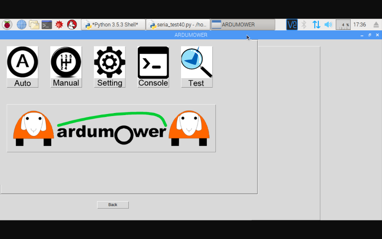

It does nothing more than sending NMEA like sentences. At the moment, my control center only support commands you can enter in serial console. To bring it further, I need to change the readSerial method of robot class. Also I need to change event trigger output (setSensorTriggerd method)

Bernard it would be great if you share how you read pfod commands via usb serial.
Attachment: https://forum.ardumower.de/data/media/kunena/attachments/2946/screenshot1.PNG/
 
Zuletzt bearbeitet von einem Moderator:
Hi.
What I'm missing in your screenshot is some status information like battery
Look at the last picture.
The big text center Box is the same as PC console and is refresh each time something occur in the mower and help to remenber error etc...
The bottom left one is the received message by the PI
The bottom Right is what send the PI
At the top there is some info like State of the mower,battery Voltage , yaw ..... (coming from NMEA message and not console and refresh each 200ms in this case ).

Exactly like you say the PI can send NMEA sentence and receive the response.

here the desciption of the 2 main Due sentence i build (State and debug)

Code:
void Robot::RaspberryPISendStat () {
  String lineToSend;
  lineToSend = "RMSTA,";
  lineToSend = lineToSend + millis();
  lineToSend = lineToSend + ",";
  lineToSend = lineToSend + stateNames[stateCurr];
  lineToSend = lineToSend + ",";
  lineToSend = lineToSend + odometryX;
  lineToSend = lineToSend + ",";
  lineToSend = lineToSend + odometryY;
  lineToSend = lineToSend + ",";
  lineToSend = lineToSend + prevYawCalcOdo;
  lineToSend = lineToSend + ",";
  lineToSend = lineToSend + batVoltage;
  lineToSend = lineToSend + ",";
  lineToSend = lineToSend + imu.ypr.yaw;
  lineToSend = lineToSend + ",";
  lineToSend = lineToSend + imu.ypr.pitch;
  lineToSend = lineToSend + ",";
  lineToSend = lineToSend + imu.ypr.roll;
  lineToSend = lineToSend + ",";
  MyRpi.writePi(lineToSend);
}

void Robot::RaspberryPISendDebug (String data) {
  String lineToSend;
  lineToSend = "RMDEB,";
  lineToSend = lineToSend + millis();
  lineToSend = lineToSend + ",";
  lineToSend = lineToSend + data;
  lineToSend = lineToSend + ",";
  MyRpi.writePi(lineToSend);
}

and here the PYNMEA side to decode this into the PI:

Code:
class STA(TalkerSentence):
    """ non stop message from DUE to PI  for state, localisation etc....
    """
    fields = (
        ("Millis", "millis"),
        ("State", "state"),
        ("OdometryX", "odox"),
		("OdometryY", "odoy"),
		("PrevYaw", "prevYaw"),
        ("BatVoltage", "batVoltage"),
        ("ActualYaw", "yaw"),
        ("ActualPitch", "pitch"),
        ("ActualRoll", "roll"),
        
		
    )
class DEB(TalkerSentence):
    """ message from DUE TO PI for  debug etc....
    """
    fields = (
        ("Hubtype", "Hubtype"),
        ("Debug", "debug"),
    )


class PFO(TalkerSentence):
    """ message between pi and due with same def as pfod
    """
    fields = (
        ("Command", "command"),
        ("Val1", "val1"),
		("Val2", "val2"),
		("Val3", "val3"),
		("Val4", "val4"),
		("Val5", "val5"),
		("Val6", "val6"),
		("Val7", "val7"),
		("Val8", "val8"),
		("Val9", "val9"),
		("Val10", "val10"),
		
    )


Be carreful that i use a PFOD like for command only and it's more complex to directly use the Pfod class.

I add comment into the DUE code and try to post it as soon as possible (It's my version of AZURIT and it work only with DUE and odometry. but can be tested directly on table)

By.
 
Hi,

looks like great progress from Bernard and Paddy, thanks sharing it here !
It also gives me better understanding why nmea was chosen as new protocol. looks like it is used by others too which is great
@Markus would you mind adding $RMVEL: as velovity message to the commands list ? That way I could add my work at a later point in time ( when show able)
Twist would be a direction command (linear x,y,z, angular x,y,z with floats 0.0 -> 1.0 ) as $RMVEL: 1.0 would move one forward or $RMVEL: 0.0, 0.0,0.0,0.5 would be a 90% degree turn around x axis as left goes 50% forward and right 50% back. ok ?

V
 
Oben