Problems Ardumower RTK/GPS KIT PCB 1.3 and DUE R3

Vic

Member
Hi / Guten Tag

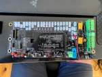
Ich baue ein ARdumower Complete-Kit, aber ich habe problem. Bin dankbar, wenn du mir helfen und herausfinden kannst, was los ist. Alle Lötungen usw. sehen in Ordnung aus und haben RK3 und TX3 eingeschaltet, wie im Video und im Handbuch beschrieben.

Ich was test und haben eine signal (alarm.) Alles lampen/dioden fungiret inkludiren 3.3 und 5V und ich was fixen 9V vor JP1 "Jumper". Aber ich finde das alarm nicht gut und connected zum PC und Alarm stops und das 3.3V and 5V diode not fungiren nur.

Ich unmontired alles komponenten und tried jeden tag mit zusammensvetsen. Aber ich kan nicht gebe die diode fur 3.3 und 5V zu funktioniren.

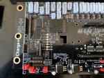
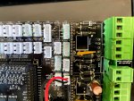
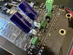
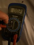
Ich habe die beiden Sicherungen EF1 und EF2 überprüft und sie sind ganz. Ich habe 9V nach aus dem Power Board. Ab 1,5 A Sicherung bete ich 7,1V.

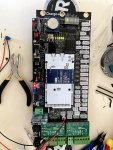
Aber das DUE R3- Carte will nicht starten, es scheint keinen Strom zu bekommen. Ich teste gemessen am blauen "Ding" und dort habe ich keinen Strom?

Was ist fehl???
Das Problem liegt auch bei beiden Sicherungen
EF1 unt EF2 Sicherung


Anhänge

  • IMG_7754.jpg
    IMG_7754.jpg
    1,1 MB · Aufrufe: 25
  • IMG_7756.jpg
    IMG_7756.jpg
    1,2 MB · Aufrufe: 27
  • IMG_7755.jpg
    IMG_7755.jpg
    186 KB · Aufrufe: 29
Ok, here is the page of interest in the schematics and the second picture below about the corresponding areas and components. It seems that the first thing between 9V and 5V/3,3V is the F1 1,5A fuse. Which would make a lot of sense if it was blown. You can test fuse with multimeter resistance settings. Take the fuse out completely and then test it with resistance settings, if you get more resistance than about the 0.0 then the fuse is blown. If resistance is 0 fuse is in working order.

If it's not the F1. I suggest you study the schematics and try to go on from there step by step to see where the circuit is broken for the 5V and 3,3V. If you are not experienced with making measurements with multimeter, there are many tutorials available in youtube. Disclaimer, don't do it if you are not positive about it and don't listen to my advice. I'm not an electronics expert. ;)

ardumower_schematics3Vand5V.PNG

IMG_20200701_000155.jpg
 
Hi ! Thank you for god answer! I was try measure the small OMT 1.5A fuse and nothing happens. I do not got even 0.00. The multimeeter only say 1 as always when turned ON. I was measured a glassfuse and this say 0.02.

I think if my multimeter not react on the fuse it’s not working, correct?

i sen image !

thax again!
 

Anhänge

  • 9DB7BECD-F982-4BD3-B2E9-175F44BAA695.jpeg
    9DB7BECD-F982-4BD3-B2E9-175F44BAA695.jpeg
    239,7 KB · Aufrufe: 11
  • image.jpg
    image.jpg
    1,6 MB · Aufrufe: 11
  • image.jpg
    image.jpg
    1,6 MB · Aufrufe: 11
I'm not familiar with the multimeter you are using, but I'd say it's pretty certain that the fuse has been blown. I would imagine you'll be in full speed after getting a new one and replacing it. But what caused it to blow is another matter. I would order a nice little pile in case you have some kind of problem in the dc-dc 24->9v converted or somewhere else on the board. But hopefully it is just a "random short" and replacing will get you going!

And while your at it order some class fuses for 5A and 10A too. Especially the EF2 fuse in the original starter kit has a 5A and I burned through a couple until I found out that EF2 is 10A and EF1 5A in many documents. 5A for EF2 is too little in the random cases where the robot goes uphill, gets stuck on branch or something and the mowing plate hits something very thick. All motors and components working at full power and the 5A is goner.
 
Zuletzt bearbeitet:
Hehe thx 🙏 yes I was already order fuses and a bunch of then 😂 orderd also 2.5 A in 7,9 mm. I also orders a pack of 100 different glassfuses too. I was think like you did. 😆 nice good to know about EF1 /EF2. In 2 days I get the fuses and going to test and also hope it was a regular blown 😃 Going to read about the twisten spin-pin on RX/TX 3 for GPS thats maby wrong in the other forum.

thx again!
 
Hi Viktor,
if you turn on your multimeter, always test it before using it by putting the probes together. Instead of the I (=Infinite) you should see 0.0. If this works you can check your fuses, resistors and so on.
 
Ich würde mit deinem Multimeter auf Diode, (das mit dem Pfeil), stellen oder auf Durchgang. So mache ich das, meiner hat einen Pipser damit gehts einfacher.
 
Hi, Das 3.3VP and 5VP diode lichten korrekt mit neues 1.5 A fuse F1.

Aber venn anslutas USB zum DUE R3 Karte das middle 3.3 V and 5.5 V Lichten für 2 sekunden. Dann es nicht shine green.

Ich kann nicht das USB in Arduino finden. Ich habe testen zu connect in Windows 10 und Mac.

Es ist ein fuse to R3 DIE karte or ist diese karte nicht fungiert?
Was kann das error be?
 

Anhänge

  • CAFB6884-0B0B-4408-9003-FDD50DF97515.jpeg
    CAFB6884-0B0B-4408-9003-FDD50DF97515.jpeg
    394,2 KB · Aufrufe: 15
Ich würde mit deinem Multimeter auf Diode, (das mit dem Pfeil), stellen oder auf Durchgang. So mache ich das, meiner hat einen Pipser damit gehts einfacher.
Ich bin nicht so gut in German so ich ferste nicht exakt. Was ist Durchgang (nicht ström connected to karte und Ohm test mot multimeter an Diode? Was ist ein Pipser?


Ist ein long video 😊
 
Zuletzt bearbeitet:
You also could switch your multimeter to the "diode" Setting. If there is a connection (Durchgang) between the probes than you will hear a beep (Piepser).
 
You should be able to see the Arduino Due in windows even if it is not connected to the board. Arduino Ide usually needs some extra libraries installed to program DUE, if you are trying it for the first time. https://www.arduino.cc/en/guide/libraries , but the IDE usually has suggested automatically for me to install the latest libraries, when connecting first time.

But of course there is the sad possibility that, whatever blew the 1,5A might have done some other damage too, including the Due board. :/
 
Hi, I think it's my Due r3 board that is not working because that board won´t light up even with USB connected. I have ordered a new R3 board now. I have also changed all 22 uF 63V and 10uF 63V but that did not help so I'm sure it has to be damaged R3 board. I threw it to the bin.
 
Installed mega 2560 and seems to work. The r3 board damaged. What do I need to do to get this working. I have was flash software before I was connect Arduino 2560. does GPS and everything work with Mega 2560? Or connect this later on?
 
NEED HEEEELP!!!


I was now got new DUE R3 from Mantronics and I was connected this and it was sound *POFF* and something in DUE card got warm and green-yellow diodes shine not so strong after connecting 24 V battery.

Where can the failure be. I have a extra DUE card but does not want to burn one more. It is strange that it works with old MEGA 2560 card??!
 
Hello first remove all components, do not connect a battery, even the Adruino try to take several macro shots of the circuit board before you go ahead and break even more.Pics for front and Back side. i hope you we can help.
 
Hi,

Here coming some photos.
 

Anhänge

  • IMG_8450.jpg
    IMG_8450.jpg
    1,9 MB · Aufrufe: 24
  • IMG_8449.jpg
    IMG_8449.jpg
    1,9 MB · Aufrufe: 24
  • IMG_8451.jpg
    IMG_8451.jpg
    1,7 MB · Aufrufe: 24
  • IMG_8452.jpg
    IMG_8452.jpg
    1,5 MB · Aufrufe: 19
  • IMG_8453.jpg
    IMG_8453.jpg
    1,6 MB · Aufrufe: 19
  • IMG_8454.jpg
    IMG_8454.jpg
    1,8 MB · Aufrufe: 19
  • IMG_8455.jpg
    IMG_8455.jpg
    1,9 MB · Aufrufe: 20
  • IMG_8456.jpg
    IMG_8456.jpg
    1,9 MB · Aufrufe: 20
  • IMG_8457.jpg
    IMG_8457.jpg
    1,1 MB · Aufrufe: 21
  • IMG_8458.jpg
    IMG_8458.jpg
    1,4 MB · Aufrufe: 21
I have now done a completely new PCB with all new parts! I followed every step in the german videos and changed jumpers to Sunray version. And have NONE Jumper on JP13/backside. https://wiki.ardumower.de/index.php?title=Ardumower_Sunray#Bluetooth_BLE_UART_module

Everything works and lights BUT the BIIIGGG!! Problem is that the DUE R3 Board does not work correctly and I can not get firmware to work , It was some Poff and smell little but still working. And then I can connect but not upload nothing to the board. It's working but not working. ***** Im doing wrong ?? When I take a brand new R3 card and does not connect this to PCB, then I can upload firmware/ Sunray but it going to POFF when put it in... I have followed Sunray info and changed RX3/TX3 pins crossed and they are not touching..


PLEASE GUYS, some instruction or something is really wrong.!!??
 
What happened here?
img_01.jpg

Some contacts look like if too much solder was used, do the contacts come together somewhere?
img_02.JPG

How do you solder? I solder at 330 degrees and the tip is 4 to 5 seconds on the component so that it does not overheat.

What exactly got warm when you first started and do you still know where it smelled?
 
Oben