Motoren reagieren nicht

senil

Member
Hallo,
Mal sehen, ob mir jemand mit einer wohltĂ€tigen Seele helfen kann. 😔

Ich habe Ardumower mit bĂŒrstenlosen Motoren und RTK-GPS-basiert.
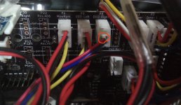
Treiber BLA V1.0 (Stand 10.01.2021) + BL V1.1 (Stand 20.04.2021)
Womit ich die 680 Ohm WiderstÀnde in die BLA gelötet habe.
1646829526559.png


Ich habe auch die Kondensatoren auf der Platine gelötet.Anhang anzeigen 3713

1646829636444.png

Ich habe es geschafft, dass das Board reagiert, die 9 Pieptöne ausgibt und die mobile APP erkennt es.
Der Akku wird aufgeladen und alles scheint in Ordnung zu sein, ich sehe keine sichtbaren Fehler in den Protokollen.
Aber wenn Sie versuchen, den Test mit AT-E auf der Konsole durchzufĂŒhren, bewegt es die RĂ€der nicht oder gibt Fehler im Prozess.

Ich hĂ€nge das Protokoll an, das ich auf der Konsole bekomme. Sowie die Konfiguration, die ich in config.h eingefĂŒgt habe

Weißt du, was ich falsch mache?
Vielen Dank im Voraus.
 

AnhÀnge

  • log.txt
    4,8 KB · Aufrufe: 19
Die config.h fehlt und irgendwas passt zumindest laut WIKI nicht:
Du hast den Brushless Adapter V1.1 wie du ja selber schreibst.

WIKI:
if you use ArduMower Brushless Adapter V1.0 (Stand10.01.2021):


The odometry divider on PCB 1.x caused a problem with the BL odometry signal. The ArduMower will drive not synchronized, one wheel is slower. You can fix it with a 220nF an each ot the odometry inputs. Take care that you use the latest version of sunray SW. Not needed for Brushless Adapter V1.1 or higher.
 
Hallo Kermy,
Danke, dass du mir geantwortet hast.
Es ist ersichtlich, dass die Datei config.h nicht unterstĂŒtzt wird, ich habe sie stattdessen als txt eingefĂŒgt.

Die Kombination der Versionen, die ich habe, ist diese:

BL V1.1
1646908732105.png

BLA V1.0
1646908848244.png

Sollen diese Parameter nicht fĂŒr diese Kombination verwendet werden?:
1646908932681.png
Und
1646909072439.png

BL soll sich auf die Motortreiber beziehen und BLA auf den Adapter, oder?

Wenn nicht, habe ich es wohl falsch verstanden und muss die 220nF und die WiderstÀnde entfernen.

Danke fĂŒrs Helfen. 🙏

PD: Ich verwende Version Sunray-1.0.230
 

AnhÀnge

  • config.txt
    29,8 KB · Aufrufe: 8
Hallo,
Ja, tut mir leid, dass ich aus dem GedÀchtnis gesprochen habe.
Ich gebe Ihnen die Nachricht weiter, die ich bekomme, wenn ich AT + E mache:

0:0:28 ctlDur=0.02 op=0 freem=245875 sp=200014CC volt=28.22 chg=0.01 tg=0.00,0.00 x=0.00 y=0.00 delta=-0.38 tow=402542400 lon=0.00000000 lat=0.00000000 h=0.0 n=0.00 e=0.00 d=0.00 sol=0 age=28.49
0:0:33 ctlDur=0.02 op=0 freem=245875 sp=20001688 volt=28.22 chg=0.01 tg=0.00,0.00 x=0.00 y=0.00 delta=-0.39 tow=402547400 lon=0.00000000 lat=0.00000000 h=0.0 n=0.00 e=0.00 d=0.00 sol=0 age=33.50
CON:AT+E
motor test - 10 revolutions
t=0 ticks Left=0 Right=0 current Left=0.11 Right=0.11
t=1 ticks Left=0 Right=0 current Left=0.11 Right=0.11
t=2 ticks Left=0 Right=0 current Left=0.13 Right=0.08
t=3 ticks Left=0 Right=0 current Left=0.13 Right=0.05
t=4 ticks Left=0 Right=0 current Left=0.14 Right=0.08
t=5 ticks Left=0 Right=0 current Left=0.10 Right=0.17

....

t=278 ticks Left=0 Right=0 current Left=0.11 Right=0.09
t=279 ticks Left=0 Right=0 current Left=0.14 Right=0.08
t=280 ticks Left=0 Right=0 current Left=0.14 Right=0.72
t=281 ticks Left=0 Right=0 current Left=0.14 Right=0.06
t=282 ticks Left=0 Right=0 current Left=0.06 Right=0.09
t=283 ticks Left=0 Right=0 current Left=0.08 Right=0.10
t=284 ticks Left=0 Right=0 current Left=0.09 Right=0.08
t=285 ticks Left=0 Right=0 current Left=0.13 Right=0.08
t=286 ticks Left=0 Right=0 current Left=0.08 Right=0.10
t=287 ticks Left=0 Right=0 current Left=0.13 Right=0.13
t=288 ticks Left=0 Right=0 current Left=0.13 Right=0.10
t=289 ticks Left=0 Right=0 current Left=0.10 Right=0.04
t=290 ticks Left=0 Right=0 current Left=0.11 Right=0.11
t=291 ticks Left=0 Right=0 current Left=0.14 Right=0.14
t=292 ticks Left=0 Right=0 current Left=0.09 Right=0.10

....


Ich musste es anhalten, weil es stÀndig weitergeht und sich die RÀder nicht bewegen.

Ich hÀnge auch das Protokoll an, das auf der SD-Festplatte herauskommt.

Vom Tablet habe ich dieses Fenster mit diesen Daten:
1646928615024.png

1646928742020.png
1646928764629.png

Wenn ich versuche, den Joystick zu bewegen, erzeugt er auch keine Bewegung.

Alles Gute.
 

AnhÀnge

  • test.txt
    17,5 KB · Aufrufe: 2
  • LOG1000.TXT
    4,6 KB · Aufrufe: 3
Zuletzt bearbeitet:
Hmm. OK, du hast also die Motortreiber in der Version 1.1 und das Brushless Adapter Bord in der Version 1.0
Das Brushless Adapter Bord ist das Bord was direkt auf das PCB gesteckt wird.
Wenn das so ist dann ist bei dir erst einmal soweit alles richtig, also die Kondensatoren auf dem PCB und die WiderstÀnde.

Ich bin davon ausgegangen das du das Adapterbord V 1.1 hast da du ja davon oben ein Bild gepostet hast.

In der App wird "undervoltage" angezeigt, da passt irgendwas nicht. Akkuspannung selber scheint zu passen.
Hast du die 9V korrekt eingestellt?
config.h scheint auf den ersten Blick zu passen, IMU funktioniert, GPS wird erkannt, ist aber nicht konfiguriert.
Motortest sollte aber trotzdem gehen.

Mach doch mal bitte ein Bild vom Anschluss der Motoren.
 
Hallo,
Nun, ich habe mit einem Tester nachgefragt und ich bekomme ungefÀhr 8,95, manchmal erreicht es 9, aber ich denke, es sollte kein Problem sein.
1646991017473.png

Das GPS ist eine andere Sache, die ich ĂŒberprĂŒfen muss, aber ich weiß nicht, ob es notwendig ist, den Laufradtest durchzufĂŒhren.

Ich habe die Fotos der Verbindungskabel, die ich konfiguriert habe.

1646991253475.jpeg

Die Verkabelung ist diese:

1646991859088.png

Ich habe nicht alle Stecker mit Masse verbunden, mit Masse sollte es doch reichen, oder?

Vielleicht sind sie mir ein bisschen lang, ich habe die AnschlĂŒsse genutzt, die mir im Kit gegeben wurden.

Ich habe ĂŒberprĂŒft, dass die losen DrĂ€hte nicht kurzschließen.

1646992297007.jpeg

1646992390682.png


1646993188383.jpeg
1646993215661.jpeg

Wenn Sie sehen, dass ein Foto nicht gut aussieht, lassen Sie es mich wissen und ich werde mehr senden.

Danke sehr!
 
sitzt Dein JP8 auf automatisch? Weil Du die UnterspannungsĂŒberwachung in der config.h aktiviert hast?
 
sitzt Dein JP8 auf automatisch? Weil Du die UnterspannungsĂŒberwachung in der config.h aktiviert hast?
Hallo,
Wenn ich JP8 auf Automatik habe. In welcher Zeile steht das?
Seit den Änderungen, die ich vorgenommen habe, kann ich mich nicht erinnern, diesen Parameter geĂ€ndert zu haben.
Danke sehr.
 
sitzt Dein JP8 auf automatisch? Weil Du die UnterspannungsĂŒberwachung in der config.h aktiviert hast?

Meinst du diese Zeile?
Muss ich die Zeilen kommentieren, wenn ich den JP8-Jumper automatisch aktiviere?

// https://wiki.ardumower.de/index.php?title=Ardumower_Sunray#Automatic_battery_switch_off
#define BAT_SWITCH_OFF_IDLE false // switch off if idle (JP8 must be set to autom.)
#define BAT_SWITCH_OFF_UNDERVOLTAGE true // switch off if undervoltage (JP8 must be set to autom.)

Danke sehr.
 
Zuletzt bearbeitet:
und ich meine den Jumper 8 auf dem Board (links neben dem großen Relais), ob dieser auf Automatik gesteckt ist.
Das "undervoltage" in der App kommt mir so komisch vor, das sollte da nicht stehen, daher meine Frage....
 
Hallo,
Ich habe diesen Fehler behoben, aber es funktioniert immer noch nicht.
Ich habe sogar die DrĂ€hte gekĂŒrzt und ĂŒberprĂŒft, ob alles in Ordnung ist, aber ich stecke immer noch fest.
Vielen Dank fĂŒr die Bewertung.
Alles Gute.
 
und ich meine den Jumper 8 auf dem Board (links neben dem großen Relais), ob dieser auf Automatik gesteckt ist.
Das "undervoltage" in der App kommt mir so komisch vor, das sollte da nicht stehen, daher meine Frage....
Hallo,
Ja, JP8 ist auf automatisch eingestellt, wie in den HandbĂŒchern empfohlen.
Was soll ich in die config.h schreiben, wenn ich es so belasse?
Danke sehr.
 
Hi senil, den Odometrie Test musst du ohne die IMU machen.

Siehe hier:

Odometry test​

Before connecting GPS, verify the odometry of your motors! If you are unable to smoothly steer the robot via the App manually, this will probably fix it!

Both, the robot's motor odometry and GPS-RTK are used to localize the robot. Therefore, it is important to verify that the odometry is working correctly as shown below.

  • Make sure IMU and GPS are not connected
  • Make sure the robots tires can move freely in the air
  • Start Arduino IDE, choose the UART port (Tools->Port from the menu)
  • Choose Tools->Serial Monitor from the menu, and send 'AT+E' (ENTER) to the robot (115200 baud). The motor test will start and both motors will rotate 10 times.
Motor test video link: https://drive.google.com/open?id=1ejT8j1Ioq8bDpk3RmWuki5KqI9K1Jq9h

Sunray motortest1.jpg Sunray motortest2.jpg

In this motor test, both gear motors will rotate approx. 10 times. If they rotate 12 or 8 times you will have to adjust the odometry settings in config.h.

Finally, the motors should be manually controllable very smoothly as seen in this video:

Additionally, you can verify the correct odometry configuration via the App. Start the phone app and follow the steps below to verify that your mower odometry is configured correctly. For this test, make sure that your RTK is turned off (e.g. RTK base module is turned OFF)!

PCB

Fixing motor directions (forward/backwards/left/right):

  1. To make one motor turn in the opposite direction you swap the red (+) and black (-) wires of that motor.
  2. If (after fixing the motor directions) robot turns into wrong side (left instead of right and vice versa), you swap the left and right motor (and odometry) connections (left motor becomes right motor and vice versa). After swapping left and right motor connections, you fix the turning direction again (1.)
So you will do to a combination of 1. and 2. to get it correctly.

Interpretation of the robot symbol within the App:

  1. The black line marker inside the white robot circle symbol marks the robot front side. So, the marker always points to the direction the robot would move if steering forward.
  2. The steering control (virtual joystick) works like this: touching up is forward and touching down is backwards.
 
Wenn die Motoren nicht drehen wĂŒrde ich als erste messen ob ĂŒberhaupt 24 Volt an den Motortreiben vorhanden sind. Dann die Sicherungen ĂŒberprĂŒfen.
Dann werden die Dioden der Motorschutzschaltung durchgemessen usw, Geht den der MĂ€hmotor wenigstens, kann in der App eingeschaltet werden.
 
Hi senil, den Odometrie Test musst du ohne die IMU machen.

Siehe hier:

Odometry test​

Before connecting GPS, verify the odometry of your motors! If you are unable to smoothly steer the robot via the App manually, this will probably fix it!

Both, the robot's motor odometry and GPS-RTK are used to localize the robot. Therefore, it is important to verify that the odometry is working correctly as shown below.

  • Make sure IMU and GPS are not connected
Ich nehme an, Sie beziehen sich auf die Trennung ĂŒber Hardware. Ich habe beide ausgesteckt, einschließlich Jumper JC2.
1647254903658.jpeg
  • Make sure the robots tires can move freely in the air
  • Start Arduino IDE, choose the UART port (Tools->Port from the menu)
  • Choose Tools->Serial Monitor from the menu, and send 'AT+E' (ENTER) to the robot (115200 baud). The motor test will start and both motors will rotate 10 times.
Ich habe dies getan, aber die Motoren bewegen sich immer noch nicht.
Ich hÀnge die test.txt-Datei an.
Motor test video link: https://drive.google.com/open?id=1ejT8j1Ioq8bDpk3RmWuki5KqI9K1Jq9h

Sunray motortest1.jpg Sunray motortest2.jpg

In this motor test, both gear motors will rotate approx. 10 times. If they rotate 12 or 8 times you will have to adjust the odometry settings in config.h.

Finally, the motors should be manually controllable very smoothly as seen in this video:

Additionally, you can verify the correct odometry configuration via the App. Start the phone app and follow the steps below to verify that your mower odometry is configured correctly. For this test, make sure that your RTK is turned off (e.g. RTK base module is turned OFF)!

PCB

Fixing motor directions (forward/backwards/left/right):

  1. To make one motor turn in the opposite direction you swap the red (+) and black (-) wires of that motor.
  2. If (after fixing the motor directions) robot turns into wrong side (left instead of right and vice versa), you swap the left and right motor (and odometry) connections (left motor becomes right motor and vice versa). After swapping left and right motor connections, you fix the turning direction again (1.)
So you will do to a combination of 1. and 2. to get it correctly.

Interpretation of the robot symbol within the App:

  1. The black line marker inside the white robot circle symbol marks the robot front side. So, the marker always points to the direction the robot would move if steering forward.
  2. The steering control (virtual joystick) works like this: touching up is forward and touching down is backwards.
Ich fĂŒrchte, ich kann letzteres nicht tun, ohne es geschafft zu haben, ersteres zum Laufen zu bringen.

Die Wahrheit ist, dass ich das schon einmal gemacht hatte, aber ohne Erfolg, deshalb ging ich ins Forum. 😔
Vielen Dank fĂŒr Ihre Hilfe. (y)(y)
 

AnhÀnge

  • LOG1011.TXT
    6,8 KB · Aufrufe: 5
Wenn die Motoren nicht drehen wĂŒrde ich als erste messen ob ĂŒberhaupt 24 Volt an den Motortreiben vorhanden sind. Dann die Sicherungen ĂŒberprĂŒfen.
Dann werden die Dioden der Motorschutzschaltung durchgemessen usw, Geht den der MĂ€hmotor wenigstens, kann in der App eingeschaltet werden.
Es ist vielleicht der beste Weg, um zu sehen, wo meine Kommunikation fehlschlÀgt.
Ich werde versuchen zu sehen, wohin die 24 V gehen, da ich nicht viel Ahnung von Elektronik habe.
Ich werde Ihnen etwas sagen, sobald ich dieses Problem geklÀrt habe.

Ein Zweifel, den ich habe. Um die 24 V zu ĂŒberprĂŒfen, muss AT + E auf der Konsole verwendet werden? Oder hat es vielleicht immer Strom und der Tester wird einfach kurzerhand benutzt?

Vielen Dank fĂŒr die allgemeine UnterstĂŒtzung aller.
👌👌
 
Zuletzt bearbeitet:
Oben