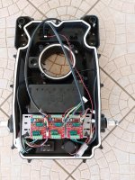
Infos zur Verkabelung eines Brushless Möhmotor

Ich hab so den Verdacht, dass es dieser Teil der motor.cpp sein könnte:

Code:
void Motor::setMowState(bool switchOn){
  if ((enableMowMotor) && (switchOn)){
    if (abs(motorMowPWMSet) > 0) return; // mowing motor already switch ON
    motorMowSpinUpTime = millis();
    if (toggleMowDir){
      // toggle mowing motor direction each mow motor start
      motorMowForwardSet = !motorMowForwardSet;
      if (motorMowForwardSet) motorMowPWMSet = pwmMaxMow; 
        else motorMowPWMSet = -pwmMaxMow; 
    }  else  {     
      motorMowPWMSet = pwmMaxMow; 
    }
  } else {
    motorMowPWMSet = 0; 
    motorMowPWMCurr = 0;
  }

   pwmSpeedOffset = 1.0; // reset Mow SpeedOffset
}
 
Hm... dieser Teil des Codes wird immer, unabhängig von Brush oder Brushless, gerechnet. Ich hätte an deiner Stelle dort gesucht, wo die
Code:
#define MOTOR_DRIVER_BRUSHLESS   1
reingeht. Evtl. in der AmRobotDriver.cpp

Das klingt für mich nach einer richtigen Suchstelle(ist im AmRobotDriver.cpp):
Code:
forwardPwmInvert = false;


Gruß
 
Wir nähern uns ;)

Die AmRobotDriver.cpp hatte ich noch nicht auf dem Schirm, weil die beim laden der Sunray.ino nicht mitgeladen wird und sie sich im SRC Ordner versteckt.

@EinEinach : vielen Dank für den Hinweis

Hab jetzt da den Regler für MOW auf CUSTOM gesetzt, jetzt funktioniert es im Prinzip.

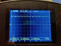
Leider kommen am RC Pin nur 2,8V (PWM) raus (laut meinem Billig Osci) und der Motor läuft daher nur auf halber Geschwindigkeit. Wenn ich 5V aus dem Labornetzteil drauf lege läuft er mit voller Geschwindigkeit.
Eventuell muss doch noch ein Level Shifter dazwischen.
 
Hm… das finde seltsam, in meiner Anwendung, ich nutze die Pins allerdings nur als digitale Outputs und nicht als PWM Ausgänge, messe ich 5V beim High Pegel
 
Da die Mähsaison ja wider begonnen hat, habe ich mit dem Projekt weiter gemacht.
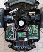
Das Gehäuse ist verbreitert und beherbergt nun 3 Mähmotoren. Das hat auch alles erstaunlich gut geklappt.
Im Moment sind die Mähmotoren noch "dumm" verkabelt.
PWM und Direction Pin hab ich auf die RC Pins gelegt. Da ich mit dem PWM pin am Eingang der Regler nicht auf die volle Drehzahl kam, habe ich jetzt ein Relais Modul dazwischen, was vom Mower PWM geschaltet wird. Dies schaltet dann die 5v, die vom Regler selber kommen, damit bekomme ich dann die volle Drehzahl.

Was jetzt fehlt ist natürlich eine Fehlererkennung.
Im Moment wäre meine Idee einen zusätzlichen Arduino oder ähnliches einzubauen, der die Drehzahl am Regler abgreift (der hat soweit ich das gesehen habe einen Ausgang dafür) und wenn die unter einen bestimmten Wert sinkt den Mower Fault triggert (der dann auch auf einem RC Pin liegen würde). So könnte ich alle drei Motoren separat überwachen.

Eventuell gibt es ja hier noch eine einfachere Lösung, die ich übersehe?
 
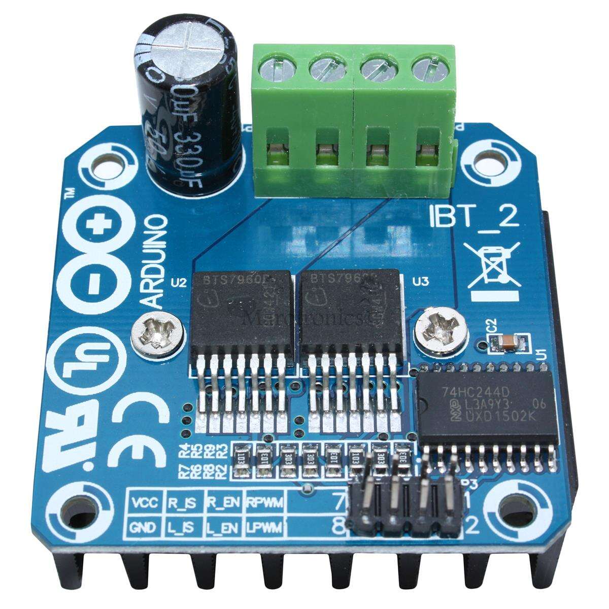
You can use 3 IBT2 driver (BTS7960)
And 3 INA226 sensor , By this way the motor speed PWM is OK and the sense feedback ovber I2C can protect the 3 mow motor on overload.
See RL1000 rebuild for more wiring info.
 
@bernard Thanks for your reply. This looks like a brushed controller though.
So I guess you adapted the Sunray Firmware to read the I2C / Amps ?
Yes exactly it's Brushed motor on Robomow RL1000 or RL2000 mower
What kind of motor did you use ?
If it's brushless one, maybe the driver have a PWM input ??

Firmware to read Mow motor sense over I2C ina226 is write for Robomow RL1000 using PCB1.3 and GCM4 and it's here:

Firmware to read Mow motor sense over I2C Ina226 and to manage 5 BTS7960 brushed motor is here, but it's a teensy code version for Teensy PCB:
 
I don't really understand what you do on the driver command :
If you use ZSX11H motor driver : It's a 3.3V driver and why did you use a relay , simply connect the PWM signal input of the driver to PCB1.3 PWM mow output ?

In the code Robomow for example:
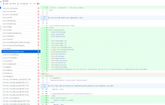
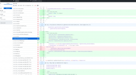
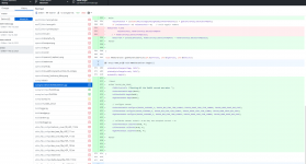
here a screen copy of the github compare with master branch:
Add the 2 file ina226.cpp and h into src/mpu folder

Do not forget to add into config.h
//on robomow you have 3 mow motor and sense is read over I2C using INA226 module
#define INA226_MOW_SENSE true
//#define INA226_MOW_SENSE false

Change the Amrobotdriver.cpp according the 3 screen copy (Green is add and red is remove)
Adjust according how many motor you want to manage over INA226.
Do not forget to use R010 resistor on INA226 or directly order the correct one.

I hope i forget nothing.

change1.png


change2.pngchange3.png
 
Thanks a lot for your detailed answer.

That got me thinking:
I don't really understand what you do on the driver command :
If you use ZSX11H motor driver : It's a 3.3V driver and why did you use a relay , simply connect the PWM signal input of the driver to PCB1.3 PWM mow output ?
I never got the PWM input to work and tried using the 5V input instead. Of course, that would work in principle, but never reach full speed.
I overlooked that a jumper needs to be soldered onto the controller to use the PWM input. Unfortunately, it's not very well documented.
Anyway it works now.

I will order some INA226 and try to get it working.
 

Anhänge

  • 03.jpg
    03.jpg
    7,1 MB · Aufrufe: 19
  • yard driver.jpg
    yard driver.jpg
    2,5 MB · Aufrufe: 18
Zuletzt bearbeitet:
I installed a temporary solution in the meantime. To do this, I connected 3 analog current sensors to a Teensy that I had lying around. It then triggers the motor fault if the current is too high or if the currents are too far apart. It works so well that I'll leave it as is for now.
 
In the code Robomow for example:
here a screen copy of the github compare with master branch:
Add the 2 file ina226.cpp and h into src/mpu folder

Do not forget to add into config.h
//on robomow you have 3 mow motor and sense is read over I2C using INA226 module
#define INA226_MOW_SENSE true
//#define INA226_MOW_SENSE false

Change the Amrobotdriver.cpp according the 3 screen copy (Green is add and red is remove)
Adjust according how many motor you want to manage over INA226.
Do not forget to use R010 resistor on INA226 or directly order the correct one.

I hope i forget nothing.

Would this code still be somewhere available (it seems to have disappeared)? I would like to do something similar to measure battery voltage using the INA226 (on arduino due). If not, I guess I will remake something similar.

thanks

edit: nevermind found it back, will try to get it to work :)
 
Zuletzt bearbeitet:
Oben