INA 2.5A oder 5A?

holunder

Active member
Der Ladestrom vom Standardnetzteil ist mir mit den 1.5A zu gering, daher wollte ich ein größeres mit 5A nehmen. Wenn ich die Brücke beim INA entferne und ihn damit auf 5A stelle, was ändert sich dann noch alles? Irgendeinen Grund muss es ja haben das die Brücke überhaupt vorhanden ist. Ansonsten konnte man ihn ja immer auf 5A laufen lassen, auch wenn man nur das kleine Ladegerät mit ~1.5A dran hat. Oder übersehe ich da etwas?
 
dann ändert sich das Verhältnis Laststrom/Spannungsausgangssignal. Also mußt Du auch in der Software die Anpassung machen.
Gruß Fürst Ruprecht
 
habe noch mal nachgelesen: 5A Brücke offen; 2,5A Brücke geschlossen; 2 Widerstände a 0.1 Ohm. Ich gehe davon aus (das mußt Du dann mal nachmessen), daß bei offener Brücke die beiden Widerstände in Reihe geschaltet sind und bei geschlossener Brücke einer überbrückt wird. Dann mußt Du in der Software bei 5A-Einstellung den Stromwert verdoppeln -> I_neu = I_alt *2 (Der Spannungsabfall bei konstantem Stromwett am Meßwiderstand halbiert sich)
Gruß Fürst Ruprecht
 
Also nur Brücke schließen und in der Config.h entsprechend anpassen.
Aber warum stellt man ihn nicht standardmäßig auf 5A? Wird die Messung ungenauer? oder hat es noch andere "Nachteile"? Es muss ja einen Grund haben. Insbesondere da die INA auf der PCB 1.4 integriert ist; eine Einstellung auf 5A werkseitig wäre technisch also kein Problem gewesen. Warum also die Unterscheidung zwischen 2.5A und 5A und nicht grundsätzlich auf 5A?

//#define CURRENT_FACTOR 0.5 // PCB1.3 (non-bridged INA169, max. 2.5A)
//#define CURRENT_FACTOR 1.0 // PCB1.3 (bridged INA169, max. 5A)
#define CURRENT_FACTOR 1.98 // PCB1.4 (non-bridged INA169, max. 2.5A)
//#define CURRENT_FACTOR 2.941 // PCB1.4 (bridged INA169, max. 5A)
 
na weil man auf den Meßfehler/-Genauigkeit schaut. Wenn Du auf 5A eingestellt hast, aber weniger als 2,5A Strom fließen, ist Deine Meßungenauigkeit absolut doppelt so hoch.
 
Die INA169 hat laut Datenblat eine Messungenauigkeit von ±0.01% bzw ±0.5%. Selbst wenn ich die verdoppel bin ich bei einer maximalen Ungenauigkeit von 1% was bei der Anwendung im Ardumower völlig zu vernachlässigen wäre.
 
Ja, das mag so sein, habe ich jetzt nicht nachgelesen. Aber das Ina-Ausgangssignal ist nur halb so hoch und der AD-Wandler des Microcontroller hat einen deutlich größeren Fehler. Ob das dann entscheidend ist, muß man sicherlich nochmal prüfen. Daher finde ich die INA-Typen mit digitaler Schnittstelle so interessant.
In Azurit werden ja die Nichtlinearitäten der AD-Wandler ausgemessen und im Speicher zur Korrektur abgelegt - also sehen das andere anders.
Ich sehe es auch nicht so eng, wollte nur auf die Zusammenhänge hinweisen (was nicht zwangsläufig alles richtig sein muß).
Gruß Fürst Ruprecht
 
sinnigerweise sollte man die Sicherung EF1 (standardmäßig 3A T) gegen eine mit ~6A T tauschen. Sinnvoll wäre da auch sicherlich ein Hinweis im Wiki & Anleitung
 
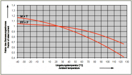
danke, habe ich grade gesehen. Wobei T5A schon sehr knapp bemessen ist. Ich würde da eher Richtung T6.2A gehen. Sicherungen neigen dazu bei höheren Temperaturen früher auszulösen. Bei 55° z.B. sinkt die Auslöseschwelle bereits um 0.85; sie löst also bereits bei 4.25A aus. Im Sommer kann es dann durchaus sein das Sicherungen zu früh auslösen


Temp-Sicherung.png
 
Le courant de charge de l'alimentation standard est trop faible pour moi avec le 1,5A, j'ai donc voulu en prendre un plus gros avec 5A. Si je retire le pont de l'INA et le met sur 5A, que changera-t-il d'autre ? Il doit y avoir une raison pour laquelle le pont est là. Sinon, vous pouvez toujours le faire fonctionner sur 5A, même si vous n'avez que le petit chargeur avec ~ 1,5A dessus. Ou est-ce que j'ai raté quelque chose ?
Bonjour,

with the power supply provided with the kit, I can load only to 0,6A (reported by the sunray firmware). It is not enough for my context, are you using the sunray firmware too? I'm wondering how do you get 1.5A ?
 
1.5A is the maximum that the standard charger can deliver. The PCB needs 0.2 to 0.3A. so the maximum charging current is 1.2A to 1.3A.
The more the battery is charged, the more the charge strength decreases. When the battery is empty, it is charged with maximum amperes; when the battery is almost full, the current drops to ~ 0.5A and less and less.

If you discharge your battery to ~ 22V, your charging current in the app will also be higher
 
1.5A est le maximum que le chargeur standard peut fournir. Le PCB a besoin de 0.2 à 0.3A. le courant de charge maximal est donc de 1,2 A à 1,3 A.
Plus la batterie est chargée, plus la force de charge diminuée. Lorsque la batterie est vide, elle est chargée avec un maximum d'ampères ; lorsque la batterie est presque pleine, le courant chute à ~ 0,5A et de moins en moins.

Si vous déchargez votre batterie à ~22V, votre courant de charge dans l'application sera également plus élevé

Thanks for the reply

But here, even if the battery is 22v, the load is only 0,6A.
I've never seen more. I'm wondering if it is a power supply issue, or a firmware limitation ?

And at the end of the load, yes, the current decreases, I can see that.
I've ordered a second power supply to make a test

Else I'm looking for a power supply of 5A, but the max that I can find is 3,5A, do you have any link to share ?

Thanks
 
Look for a charger for the Ambrogio Elite 200/250/300 or the Stiga Autoclip 500 series.

These are MeanWell power supplies with 29.4V with 5.1Ah.

What kind of battery did you use?
Is the correct PCB / INA configuration set in the config?
 
Thanks a lot for the reference @holunder ,

My battery is a home made, 7s 4p, with a BMS.

My config.h:
#define CURRENT_FACTOR 1.98 // PCB1.4 (non-bridged INA169, max. 2.5A)

for example this night:
from 22,5v to 27v takes 14h.... that looks too long in my opinion ?

I've tried to directly load it with the power supply, and looks to load much more quicker.

do you think something is slowing down the load on the pcb 1.4? Do I have something to change on the PCB or in the config.h ?

thanks
 
14 hours are long.
What kind of cells did you use in your battery? What kind of BMS do you use? How were the cells connected (welding, soldering, screwing)? The cells all had the same output voltage? Are only cells of the same capacity used?
 
Hi @holunder ,

I've welded the cells,
The BMS is a 7s 25A , this one : https://fr.aliexpress.com/item/1005001427275240.html?spm=a2g0s.9042311.0.0.76836c377WTm5B
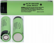
The cells are 3400 mah: Panasonic – batterie Rechargeable, 1x3.7v, 3400mah, Ncr 18650b 18650, Lithium-ion, Max 20a, Nickel, pour phares

When I plug directly the power supply to the battery, the load is very fast (I don't know how much time to full loaded it, may be 4/6h). So I'm thinking the pcb 1.4 or the firmware limit the current load ? is it possible ?
 
How were the cells connected to each other?
Did you load the cells one by one before they were assembled?

The original Panasonic cells look exactly like this:
Screenshot 2021-08-10 at 12-23-06 Messerforum Lampentester Großer Akkutest 2012 - 18650er Lith...png

The problem with Aliexpress, wish etc. is that almost only used or fake cells are sold. You will not get these cells in Europe for less than € 3.78 plus tax. If you have paid less, you can actually assume that it is not an original cell.

Take 2 or 3 cells out of your battery pack, charge them to 4.2V and do a capacity measurement.

The values that the cell must reach are as follows:

Screenshot 2021-08-10 at 12-30-15 Test Review Panasonic NCR18650B 3400mAh (Green) BudgetLightF...png


How did you weld the cells? How many amps, which pulse rate and which band (thick) did you use?

Your BMS has an end-of-charge voltage of 4.25 V (± 0.025 V); Your battery cells may only be charged with a maximum of 4.2V. This means that the BMS is not suitable for your cells. The Panasonic NCR18650B in particular are very sensitive to overcharging.

The PCB does not regulate the current, it just switches the relay to start and stop charging. Therefore I assume that the fault is in your battery. If you charge the battery manually with the charger, it only switches off when the load goes to 0. Your BMS then tries to balance and minimally overloads all cells.
The PCB disconnects the charging current when it reaches ~ 80%
 
Thanks a lot for all this good information,

about the picture, yes, it is exactly this label on the cell.

I'm using this for welding : https://fr.aliexpress.com/item/1005002021764783.html?spm=a2g0s.9042311.0.0.4d2c6c37aVAhY6
I don't know how to answer to your questions
All the cells had the same voltage when I've welded them. But not fully loaded.

I didn't notice for the BMS, thanks to point me out that.

I have another battery to build with those cells : https://www.nkon.nl/fr/samsung-inr18650-32e-3100mah-6-4a.html
If I'm following correctly the BMS model is not suitable too for those cells.

I will try to find a better BMS, build the second battery and do some tests:


This one looks better?

Thanks a lot for all your advices.
 
Zuletzt bearbeitet:
Oben