Starsurfer78
Active member
Moin,
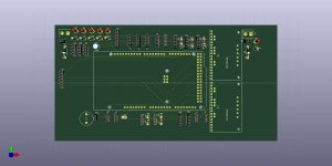
ich langweile mich zur Zeit, da ich auf meine PCB warte und wollte mich in der Zwischenzeit ein wenig in Kicad einarbeiten.
Es soll irgendwann mal eine einfache PCB werden, die nur das nötigste Enthält und die ich vielleicht zum Testen und spielen benutzen kann.
Wenn die mal kaputtgeht, tut das nicht so weh")
Aber da ich eigentlich keine Ahnung davon habe, wäre es super, wenn sich Leute mit Ahnung mal den Schaltplan ansehen könnten.
Die PCB soll nur mit dem DUE und den Brushless Board Adapter benutzt werden.
Würde mich über Tipps und Verbesserungsvorschläge freuen.
ich langweile mich zur Zeit, da ich auf meine PCB warte und wollte mich in der Zwischenzeit ein wenig in Kicad einarbeiten.
Es soll irgendwann mal eine einfache PCB werden, die nur das nötigste Enthält und die ich vielleicht zum Testen und spielen benutzen kann.
Wenn die mal kaputtgeht, tut das nicht so weh
Aber da ich eigentlich keine Ahnung davon habe, wäre es super, wenn sich Leute mit Ahnung mal den Schaltplan ansehen könnten.
Die PCB soll nur mit dem DUE und den Brushless Board Adapter benutzt werden.
Würde mich über Tipps und Verbesserungsvorschläge freuen.