As I have said earlier I took just about everything on video when I was making my robot. This may really take some time, but the first 4Gb resulted in the video as below. It is clear that I'm not working in studio grade environment nor am I an expert videoeditor, but I hope this will help someone when completed. I have still 80Gb to edit and it's everything, working on the case, putting pcb into the case with all sensors etc etc. Not just soldering the PCB. Ardumower project will of course have the right to use the videos as desired.
Du verwendest einen veralteten Browser. Es ist möglich, dass diese oder andere Websites nicht korrekt angezeigt werden.
Du solltest ein Upgrade durchführen oder einen alternativen Browser verwenden.
Du solltest ein Upgrade durchführen oder einen alternativen Browser verwenden.
English videos, part 1 for review
- Ersteller markor
- Erstellt am
Thanks, happy to hear that! I actually have the second video ready and I have created a playlist for all the videos to come.
I will add all videos to Ardumower Playlist . However I can't give any timetable for next videos, but I'm trying to have them out as soon as I can.
I will add all videos to Ardumower Playlist . However I can't give any timetable for next videos, but I'm trying to have them out as soon as I can.

Thanks. Yes it matters. Mine is correct at least with Azurit firmware that I am using. I think it was a mistake in the original video or something has changed during the years. My mower is already finished and the bluetooth works as shown.
BTW. I was crazy enough to push the 4th video out. It's a long one, lot's of diodes to go!") It's uploading now and will be autopublished after HD conversion in about 6 hours and 30minutes.
It's uploading now and will be autopublished after HD conversion in about 6 hours and 30minutes.
BTW. I was crazy enough to push the 4th video out. It's a long one, lot's of diodes to go!
It's uploading now and will be autopublished after HD conversion in about 6 hours and 30minutes.Vic
Member
Wow nice work! Thank you!  I was do some diod from german video. Yesterday I was also look little at German video before yours. I put some stift in wrong side of the Bord, then I go to bed
  Today I was starting fixing this and tomorrow/ today I think I going to finish with everything.
I was sit up all night and soldering
I going to do video when finished.
I going to flash Sunray firmware because I have GPS base version.
Was find also some nice weels in a customers store.
I was do some diod from german video. Yesterday I was also look little at German video before yours. I put some stift in wrong side of the Bord, then I go to bed Today I was starting fixing this and tomorrow/ today I think I going to finish with everything. I was sit up all night and soldering
I going to do video when finished.
I going to flash Sunray firmware because I have GPS base version.
Was find also some nice weels in a customers store.
Anhänge
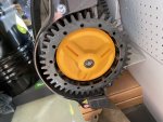
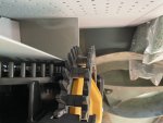
Whow, nice wheels!! Most of the components can be soldered on eather side, but it's recommended to use certain order as shown in the videos to avoid "collusion" of two components. There are some places where the soldering order and placement matters. And I know your feeling, it's very easy to get carried away on project like this!
Vic
Member
Ok yes nice! I have to try to do similar weels I think.
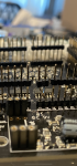
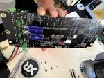
I just testing the cards here. Everything seems to work but it alarm after insert the Due RT3 board and the smallest board to the right of rt board and battery to left side of PCB. Do I have to switch from Dauer ON to Ardumower pin? (I tried this, not helped) First it was constant alarm and now it's like pip, pip and not enough electric. It's 9V from out on electricboard. Every diod working before connecting DUE and small boards/ motherboards.
Also wonder if it's correct as I did here with switch pins. See image.
Anhänge
Zuletzt bearbeitet:

In the first picture the pins do not look right at all. It's very weird if you need to do this. The gps tx and rx can be switched through wireing if needed. But unlike I2C devises, the gps is on different bus and you are supposed to connect rx to tx and tx to rx. It's especially bad if the pins are touching each other. All pins should go straight up to due. I don't have the new gps version, but don't look right to me in any case.
Second picture, if you mean the transistors, the orientation does not matter. All seems good there.
Second picture, if you mean the transistors, the orientation does not matter. All seems good there.
Ok, I see. It seems to be from the english manual in thread https://forum.ardumower.de/threads/can-i-help-with-the-complete-english-instructions.23770/ . I have posted my question in there. Let's continue the discussion there.
Vic
Member
I tried little more today and now it's not any sound or alarm when I connect and only 24 V is green light. Yesterday all was working with Alarm.
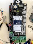
It seams that the DUE Card does not get enough electric. When connecting directly to DC-adapter to DUE-card it does only blink low electric and pretty fast. I was try resetbutton on DUE card. Also tried different position of jumpers. I have also tried PCB without all cards and with same result. (=only 24 V and Dual1+Dual2)
Yesterday I was see I was forgot to put the the C1 in place. (see image) Now its there but same result.
PC does not now recognise any device when I plug in the USB (programming port). I have also tried in MAC. (same issue)
Anhänge

Have you made sure u followed all the steps in these:
 wiki.ardumower.de
Also I can't see the P49 at the back of the board if it has emergency switch cables or jumpwire, if you are connecting the emergency switch between the battery.
Whichever way you decide to use, you must have the circuit closed on P49. Just a little piece of wire from + to -. Otherwise the juice is not going through the emergency switch connector.
Edit: Never mind, I was blind. The jumper wire seems to be there after all. Please see the tutorial and checklist next. Stop at the point in the video where the lights should come on and let's see then what to check? Don't have a lot of time, but don't see anything obviously wrong.
If my memory serves well, the lights should come on even without programming the due, so checking the hardware is the key.
PCB 1.3 (English) – www.wiki.ardumower.de
Whichever way you decide to use, you must have the circuit closed on P49. Just a little piece of wire from + to -. Otherwise the juice is not going through the emergency switch connector.
Edit: Never mind, I was blind. The jumper wire seems to be there after all. Please see the tutorial and checklist next. Stop at the point in the video where the lights should come on and let's see then what to check? Don't have a lot of time, but don't see anything obviously wrong.
If my memory serves well, the lights should come on even without programming the due, so checking the hardware is the key.
Zuletzt bearbeitet:
Vic
Member
Hi,
Yes I was followed all steps there and it Worked untill the end (all diode was green), but I was think the alarm signal from buzzer was something wrong. Because of that I was disconnect all chips.
Then now when assemble it again The strange thing is that it does not work anymore. After I put JP1 jumper in for 9 V it does not happen so much. No sign of 3.3 V and 5V diode.
I can not see if any fuse is damage. I can try change fuse between ef1/ef2 again. (the 2 glass fuses)
Update: Was tried with both fuse in and no 3.3 and 5V
.
Can it be the blue ”transformator” what is damage?
Zuletzt bearbeitet: