Can I help with the Complete English Instructions?

robind

New member
I'm about to build my first ardumower, and I'd love to take the opportunity to improve the English instructions.

I know that there is a PDF available with the German instructions, and I've heard rumor that there's an English version in progress. Can I get whatever is available for this, so that I can work with it, and improve it? I'd love to contribute to building a set of English Instructions.

If I'm missing some great forum threads which already post this information, please let me know. I've searched a lot, but did not find any.
 
Thanks for your interest in contributing to the project! I'll send you a private message so you can help with the tanslations...
 
Just found this thread. I have taken video of every step during the build, including chasis and putting all together. I've setup an playlist for the videos, which already has 2 first videos. Ardumower project has of course the rights to use these as you see fit.

Edit: I have no studio equipment, nor am I an pro in editing videos, but I think they get the job done. ;)


@greymfm76 Question about the "Step 12: Arduino pin headers". Why should the pins be twisted like this? I don't know if this a very old or very new board, but I have 3 boards bought over couple of years and I'm using straigth pins on all. Is this a confusion between I2C and serial bus? In I2C bus you must connect SDA to SDA and SCL to SCL, but in serial bus you are supposed to connect the TX (transmit) to RX (receive) and RX to TX.

Edit: I watched the video about twisting the pins and even his board is a correct one saying 14 GPS RX and 15 GPS TX. This must be a confusion about how to connect the cables to the device. Pins should go straigth to DUE and when connecting the GPS the correct wireing is RX to TX and TX to RX.

In any case, if there is a mistake on some boards, which I haven't come across in last few years, wouldn't it make much more sense to just switch the wireing (to WRONG order RX to RX and TX to TX) when connecting the GPS module? All in all please add at least a reminder to add some electric tape etc to make sure the pins never touch each other.

End edit.

Btw, I'm now uploading a 5th english video and the last soldering video is already on it's way. The 5th video is kind of "blooper" video, but I want to show the mistakes, so others can hopefully avoid them (the correct ways are of course there also).
 
Zuletzt bearbeitet:
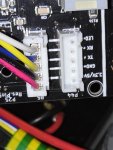
@markor I think that the problem cannot be solved by reversing the wires connecting the plug to the GPS board because the TX and RX pins for the GPS are not wired the same in the PCB Schematic.Screen Shot 2020-06-28 at 11.41.32 AM.png

If the wires were straight-through from the Arduino Mega to the GPS connector, I would say that you are correct, but because of the various other components (specifically the voltage-optional JP12), it's not possible to simply reverse the wires. It might be simply that it won't supply the correct signal voltage to a 3.3V-GPS board...but you're using 5V GPS boards....I'm don't know enough about electronics (and this schematic in particular) to guess.

In your multiple boards that you have bought over the years, are they all using GPS?

What do you think?
 
@robind This is confusing. I have 2 arduino due versions fully operational, all pins straigth in both and gps rx to tx and tx to rx and they are operating flawlessly. The other robot is actually operating totally without perimeter wire, only with the GPS. The area doesn't require pin point accuracy to work on. I have also just made additions that they can find the charging station by using gps. In the other area perimeter wire is only used for the last few meters to hit the charging station with precision. So yes, I have been using GPS and no problems what so ever with the straigth pins up. That's why I brought it up.

Heck, had to open the older one and double check. All is as I said above.

Unfortunately I don't have a microscope, but I will post some highres photos later. If I'm looking at the board correctly the Pin 15 gpsTX is going to R96 and Pin 14 gpsRX is going to R94, so it seems at this point that the pins should really be straigth.

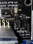
IMG_20200628_205748.jpgIMG_20200628_205627.jpgIMG_20200628_205510.jpg
 
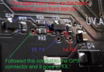
Picture 1 below. Ok, here we go as promised. In the first picture the conduits go to these punch through holes.

gpsPins_14RX15TX_1.PNG

Picture 2 below. The conduit continues on the backside of the board and go to another set of 2 holes. Starting holes on the left are mirrored from first picture because switching to the backside.

gpsPins_14RX15TX_2.PNG

Picture 3 below. Switched to front side again so the holes are mirrored from last picture again. The 15 gpsTX goes (from under Q28) to R96, which again goes to Q29 and then to R95. The 14 gpsRX goes to R94 and Q28 and from Q28 to R93. I actually followed the whole path and it goes from R93 to the gps connector TX. So the markings from board 14 gpsRX goes to connector TX which is how it should be and the pins should be connected straigth, right?

gpsPins_14RX15TX_3.PNG
 
I also see this result on 2 PCB1.3 with straight wire all work perfectly with the GPS M8N;);)
But 1 or 2 years ago, 2 other member have trouble and they need to twist the wire.
It's very old post and i can't find it again but if i remember the issue was Q28 or Q29 not solder in the correct direction :unsure: :unsure: :unsure: :unsure: .

To avoid trouble you can easily use the WLAN connector and change Serial3 to Serial1 in the code;)
If you absolute need WIFI on board change the HC05 module by ESP32 DEV KIT to have both Bluetooth and WIFI.
 
So, I'm getting close to adding those pins (recent 09/2020 board). Should I assume, soldering them straight would work? What's he consenus?
 
The problem is, the #14 is TX3, not RX3. So, not sure, how that would work with straight pins?!
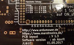
Except if you look at my first picture carefully you will see that in my board the 14 is GPSRX and 15 is GPSTX. I don't know if it is your camera, but the picture looks like that board is very old. Propably the most helpful thing would have been to keep the date of the board in the picture. I'm quite sure there has been fault boards at some time and I'd guess it has been PRE 2017 boards, but please correct me if your board is newer than 2017. All I'm sure about is that I have bought 3 boards in last few years and they have all been 2017 dated boards and they all need to have straight pins. All my mowers are working great with GPS with straight pins.

So maybe the best advice to all is to check which way the tx and rx are and if they like on my board put it straight and if they are like on your board, just twist them.

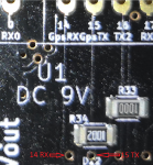
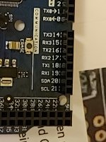
Here is yet a better picture of which are which pins:
 

Anhänge

  • tx_rx.jpg
    tx_rx.jpg
    2,1 MB · Aufrufe: 9
The problem is, the #14 is TX3, not RX3. So, not sure, how that would work with straight pins?!
Ok, Now I feel pretty stupid. I didn't have my mind in the right place. Your picture is the bottom of the Arduino board while I was talking about the Ardumower mainboard 1.3 . I've actually never even looked what the back of the Arduino board says. Sorry about the confusion, I really don't know what else to say at the moment... My gps works and I have not twisted them, but can it still be wrong? I don't know atm.
 
Hello,

I've just received my ardumower kit with pcb v1.4 from marotronics (thanks markus). I'm french but I'm fluent in technical english.
I don't know what is the state of the documentation in english version. But I could help, as I'm starting the build the full kit (with pcb v1,4, grand central & gps rtk):
- I can review the documentation
- Finish some translation if needed

Don't hesitate to ask.

P.S.: does it make sense to translate it in French ?
 
Oben