MarioFFK
Member
ESP code
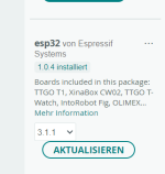
/*
ESP32-Firmware bietet:
1. BLE UART bridge (GATT server UART)
2. WiFi UART bridge (HTTP server UART)
Steps to install ESP32 for Arduino IDE 1.8.13:
1. Arduino IDE: Datei->Einstellungen: Zu Board-Manager-URLs hinzufügen:",https://dl.espressif.com/dl/package_esp32_index.json"
2. Wählen Sie „Extras->Board->Board-Manager“
3. Fügen Sie die Karte „esp32“ hinzu (WICHTIG!!! Wählen Sie v1.0.4, die neueste v1.0.6 scheint keine Verbindung zum WLAN-Zugangspunkt herzustellen!)
4. Wählen Sie Board „ESP32 Dev Module“ (wenn das Hochladen nicht funktioniert: DRÜCKEN SIE EN+BOOT, lassen Sie EN auf Ihrem ESP32 los)
5. Wählen Sie das Partitionsschema „Minimal SPIFFS“ (andernfalls kann es zu „Speicherplatzfehlern“ in der Arduino IDE kommen)
(also see: https://github.com/espressif/arduino-esp32/blob/master/docs/arduino-ide/boards_manager.md )
6. Wählen Sie Port (Windows HINWEIS: Wenn der Port nicht angezeigt wird, müssen Sie möglicherweise Treiber installieren: https://www.silabs.com/developers/usb-to-uart-bridge-vcp-drivers)
7. Wählen Sie „Extras->Bibliotheken verwalten…“
8. Add library "ESP32_HTTPS_Server 1.0.0 by Frank Hessel"
9. Bibliothek „ArduinoJson 6.18.5 von Benoit Blanchon“ und „ThingsOfValue SDK for Arduino 1.0.0 von Kyuseok Oh“ hinzufügen (nur erforderlich, wenn „USE_MQTT“ aktiviert ist)
10.Bibliothek „NimBLE-Arduino 1.3.1 by h2zero“ hinzufügen (benötigt weniger Speicher – nur erforderlich, wenn aktiviert „USE_NIM_BLE“)
11. Kopieren Sie diese Datei in „config.h“.
12. Konfigurieren Sie die folgenden Optionen und kompilieren und laden Sie schließlich dieses Projekt hoch.
wiring (also see wiring image in Github folder):
ESP32 Rx2 (GPIO16) --- Ardumower PCB1.3 Bluetooth conn RX (3.3v level)
ESP32 Tx2 (GPIO17) --- Ardumower PCB1.3 Bluetooth conn TX (3.3v level)
ESP32 GND --- Ardumower PCB1.3 Bluetooth conn GND
ESP32 5V (Vin) --- Ardumower PCB1.3 Bluetooth conn 5V
Note: ESP32 D1 Mini (china cheapo) can work as a comm/BLE chip.
Data is reported and mower can be steered using app.
Things to remember are:
- need to wait few secs after mower reboots before connecting (CRC issues)
- need to close/reopen app if the phone disconnects (CRC issues)
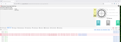
Note: Please see and ask in the forum if you experience HTTP connection issues:
https://forum.ardumower.de/threads/...d-sunray-app-verbindungsproblem-gelöst.24467/
NOTE: If your ESP32 is not available as a device, you may have to install an USB driver:
https://www.silabs.com/developers/usb-to-uart-bridge-vcp-drivers
*/
#define NAME "Ardumower"
// bluetooth low energy (BLE)
#define USE_BLE 1 // comment this line to remove BLE support
#define BLE_MTU 20 // max. transfer bytes per BLE frame
#define BLE_MIN_INTERVAL 2 // connection parameters (tuned for high speed/high power consumption - see: https://support.ambiq.com/hc/en-us/articles/115002907792-Managing-BLE-Connection-Parameters)
#define BLE_MAX_INTERVAL 10
#define BLE_LATENCY 0
#define BLE_TIMEOUT 30
//#define USE_NIM_BLE 1 // use NimBLE library (requires less memory) instead of ESP32 library?
//IP WiFi:
//#define WIFI_STATIC_IP true // activate this for static IP
#define WIFI_STATIC_IP false // activate this for dynamic IP
// if using static IP, configure IPs below
#define WIFI_STATIC_IP_LOCAL 10,0,100,11
#define WIFI_STATIC_IP_GW 10,0,100,1
#define WIFI_STATIC_IP_SUBNET 255,255,255,0
#define WIFI_STATIC_IP_DNS1 8,8,8,8
#define WIFI_STATIC_IP_DNS2 8,8,4,4
#define WIFI_STA_SSID "FRITZ!Box7590MK" // WiFi SSID (leave empty ("") to not use WiFi)
#define WIFI_STA_PSK "xxxxxxxxxxxxxxx" // WiFi password (leave empty ("") to not use WiFi)
#define WIFI_TIMEOUT_FIRST_RESPONSE 800 // fast response times (500), for more reliable choose: 800
#define WIFI_TIMEOUT_RESPONSE 400 // fast response times (100), for more reliable choose: 400
// comment this line to use HTTP, uncomment to use HTTPS
// NOTE: if using HTTPS, you also need to uncomment USE_NIM_BLE above!
#define USE_HTTPS 1
// Relay server
//
// Install this library with the Arduino Library Manager:
// ArduinoWebsockets - by Gil Maimon - https://github.com/gilmaimon/ArduinoWebsockets
//
//#define USE_RELAY
//#define RELAY_URL "wss://example.relay.mow.timotto.io/mower"
//#define RELAY_USERNAME ""
//#define RELAY_PASSWORD ""
//#define RELAY_TIMEOUT 1000
//#define RELAY_PINGWAIT 55
// MQTT server
// (subscribed topcis: '/command/start', '/command/stop', '/command/dock', '/command/reboot', '/command/shutdown', '/command/"every AT+... command supported by comm.cpp"')
// e.g. command for start over AT+... payload: /command/AT+C,-1,1,0.29,100,0,-1,-1,1
// (published topics: '/online', '/state', '/props', '/stats')
//#define USE_MQTT 1 // uncomment to activate MQTT
#define MQTT_PREFIX "/ardumower/"
#define MQTT_HOSTNAME "mqtt-server.home.lan" // IP or hostname (example: "192.168.2.60")
#define MQTT_PORT 1883
#define MQTT_CLIENT_ID NAME
#define MQTT_USERNAME ""
#define MQTT_PASSWORD ""
#define ENCRYPTION_PASSWORD 123456
#define ENCRYPTION_ENABLED true
// pin assignment
#define pinGpioRx 16 // UART2 / GPIO16 / IO16
#define pinGpioTx 17 // UART2 / GPIO17 / IO17
//#define pinGpioRx 9 // UART1 / GPIO9 / SD2
//#define pinGpioTx 10 // UART1 / GPIO10 / SD3
//#define pinGpioRx 3 // UART0 / GPIO3 / RXD0
//#define pinGpioTx 1 // UART0 / GPIO1 / TXD0
#define pinLED 2
#define CONSOLE Serial // where to send/receive console messages for debugging etc.
#define UART Serial2 // where to send/receive UART data
/*
ESP32-Firmware bietet:
1. BLE UART bridge (GATT server UART)
2. WiFi UART bridge (HTTP server UART)
Steps to install ESP32 for Arduino IDE 1.8.13:
1. Arduino IDE: Datei->Einstellungen: Zu Board-Manager-URLs hinzufügen:",https://dl.espressif.com/dl/package_esp32_index.json"
2. Wählen Sie „Extras->Board->Board-Manager“
3. Fügen Sie die Karte „esp32“ hinzu (WICHTIG!!! Wählen Sie v1.0.4, die neueste v1.0.6 scheint keine Verbindung zum WLAN-Zugangspunkt herzustellen!)
4. Wählen Sie Board „ESP32 Dev Module“ (wenn das Hochladen nicht funktioniert: DRÜCKEN SIE EN+BOOT, lassen Sie EN auf Ihrem ESP32 los)
5. Wählen Sie das Partitionsschema „Minimal SPIFFS“ (andernfalls kann es zu „Speicherplatzfehlern“ in der Arduino IDE kommen)
(also see: https://github.com/espressif/arduino-esp32/blob/master/docs/arduino-ide/boards_manager.md )
6. Wählen Sie Port (Windows HINWEIS: Wenn der Port nicht angezeigt wird, müssen Sie möglicherweise Treiber installieren: https://www.silabs.com/developers/usb-to-uart-bridge-vcp-drivers)
7. Wählen Sie „Extras->Bibliotheken verwalten…“
8. Add library "ESP32_HTTPS_Server 1.0.0 by Frank Hessel"
9. Bibliothek „ArduinoJson 6.18.5 von Benoit Blanchon“ und „ThingsOfValue SDK for Arduino 1.0.0 von Kyuseok Oh“ hinzufügen (nur erforderlich, wenn „USE_MQTT“ aktiviert ist)
10.Bibliothek „NimBLE-Arduino 1.3.1 by h2zero“ hinzufügen (benötigt weniger Speicher – nur erforderlich, wenn aktiviert „USE_NIM_BLE“)
11. Kopieren Sie diese Datei in „config.h“.
12. Konfigurieren Sie die folgenden Optionen und kompilieren und laden Sie schließlich dieses Projekt hoch.
wiring (also see wiring image in Github folder):
ESP32 Rx2 (GPIO16) --- Ardumower PCB1.3 Bluetooth conn RX (3.3v level)
ESP32 Tx2 (GPIO17) --- Ardumower PCB1.3 Bluetooth conn TX (3.3v level)
ESP32 GND --- Ardumower PCB1.3 Bluetooth conn GND
ESP32 5V (Vin) --- Ardumower PCB1.3 Bluetooth conn 5V
Note: ESP32 D1 Mini (china cheapo) can work as a comm/BLE chip.
Data is reported and mower can be steered using app.
Things to remember are:
- need to wait few secs after mower reboots before connecting (CRC issues)
- need to close/reopen app if the phone disconnects (CRC issues)
Note: Please see and ask in the forum if you experience HTTP connection issues:
https://forum.ardumower.de/threads/...d-sunray-app-verbindungsproblem-gelöst.24467/
NOTE: If your ESP32 is not available as a device, you may have to install an USB driver:
https://www.silabs.com/developers/usb-to-uart-bridge-vcp-drivers
*/
#define NAME "Ardumower"
// bluetooth low energy (BLE)
#define USE_BLE 1 // comment this line to remove BLE support
#define BLE_MTU 20 // max. transfer bytes per BLE frame
#define BLE_MIN_INTERVAL 2 // connection parameters (tuned for high speed/high power consumption - see: https://support.ambiq.com/hc/en-us/articles/115002907792-Managing-BLE-Connection-Parameters)
#define BLE_MAX_INTERVAL 10
#define BLE_LATENCY 0
#define BLE_TIMEOUT 30
//#define USE_NIM_BLE 1 // use NimBLE library (requires less memory) instead of ESP32 library?
//IP WiFi:
//#define WIFI_STATIC_IP true // activate this for static IP
#define WIFI_STATIC_IP false // activate this for dynamic IP
// if using static IP, configure IPs below
#define WIFI_STATIC_IP_LOCAL 10,0,100,11
#define WIFI_STATIC_IP_GW 10,0,100,1
#define WIFI_STATIC_IP_SUBNET 255,255,255,0
#define WIFI_STATIC_IP_DNS1 8,8,8,8
#define WIFI_STATIC_IP_DNS2 8,8,4,4
#define WIFI_STA_SSID "FRITZ!Box7590MK" // WiFi SSID (leave empty ("") to not use WiFi)
#define WIFI_STA_PSK "xxxxxxxxxxxxxxx" // WiFi password (leave empty ("") to not use WiFi)
#define WIFI_TIMEOUT_FIRST_RESPONSE 800 // fast response times (500), for more reliable choose: 800
#define WIFI_TIMEOUT_RESPONSE 400 // fast response times (100), for more reliable choose: 400
// comment this line to use HTTP, uncomment to use HTTPS
// NOTE: if using HTTPS, you also need to uncomment USE_NIM_BLE above!
#define USE_HTTPS 1
// Relay server
//
// Install this library with the Arduino Library Manager:
// ArduinoWebsockets - by Gil Maimon - https://github.com/gilmaimon/ArduinoWebsockets
//
//#define USE_RELAY
//#define RELAY_URL "wss://example.relay.mow.timotto.io/mower"
//#define RELAY_USERNAME ""
//#define RELAY_PASSWORD ""
//#define RELAY_TIMEOUT 1000
//#define RELAY_PINGWAIT 55
// MQTT server
// (subscribed topcis: '/command/start', '/command/stop', '/command/dock', '/command/reboot', '/command/shutdown', '/command/"every AT+... command supported by comm.cpp"')
// e.g. command for start over AT+... payload: /command/AT+C,-1,1,0.29,100,0,-1,-1,1
// (published topics: '/online', '/state', '/props', '/stats')
//#define USE_MQTT 1 // uncomment to activate MQTT
#define MQTT_PREFIX "/ardumower/"
#define MQTT_HOSTNAME "mqtt-server.home.lan" // IP or hostname (example: "192.168.2.60")
#define MQTT_PORT 1883
#define MQTT_CLIENT_ID NAME
#define MQTT_USERNAME ""
#define MQTT_PASSWORD ""
#define ENCRYPTION_PASSWORD 123456
#define ENCRYPTION_ENABLED true
// pin assignment
#define pinGpioRx 16 // UART2 / GPIO16 / IO16
#define pinGpioTx 17 // UART2 / GPIO17 / IO17
//#define pinGpioRx 9 // UART1 / GPIO9 / SD2
//#define pinGpioTx 10 // UART1 / GPIO10 / SD3
//#define pinGpioRx 3 // UART0 / GPIO3 / RXD0
//#define pinGpioTx 1 // UART0 / GPIO1 / TXD0
#define pinLED 2
#define CONSOLE Serial // where to send/receive console messages for debugging etc.
#define UART Serial2 // where to send/receive UART data
 geht auch nicht.