ZS-X12H Treiber und Sunray

EinEinfach

Well-known member
In diesem Thread möchte ich meine Erfahrungen mit dem Treiber ZS-X12H dokumentieren. Da ich aktuell mit dem ZS-X11D1 bei meinem Linux Mäher Probleme bei hohen Geschwindigkeiten habe (Ab 0,4m/s bekomme ich die Geschwindigkeit nicht stationär stabil). Ich denke zwar nicht, dass es am Treiber liegt, sondern eher am SerielRobotDriver, wollte ich zum Vergleich trotzdem einen anderen Treiber nehmen.

Die Erfahrungen halten sich in Grenzen, aber ich werde nach und nach hier alles ergänzen.

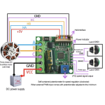
Am Laborplatz lassen sich die Motoren super mit dem Treiber drehen. Angeschlossen habe ich das wie in diesem Bild gezeigt:

Bildschirmfoto 2025-03-30 um 20.28.18.png

Vorteile:
- Sau günstig, wenn es noch weniger kosten würde, wäre es schon umsonst
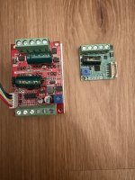
- Sehr klein (Hier ein Vergleich zum ZS-X11D1
tempImagedyyi7m.jpg

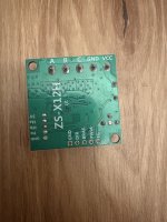
- Die gleichen Anschlussmöglichkeiten, wie der ZS-X11D1
tempImageNd5djI.jpg

Nachteile:
- Anschlussleiste für Hall-Sensoren ist kein Standard JST 2,54mm Stecker (kleiner)
- Aufgrund der maximalen Leistung für Mähmotor eher ungeeignet (max 100W)

Fortsetzung folgt...
 
In diesem Thread möchte ich meine Erfahrungen mit dem Treiber ZS-X12H dokumentieren. Da ich aktuell mit dem ZS-X11D1 bei meinem Linux Mäher Probleme bei hohen Geschwindigkeiten habe (Ab 0,4m/s bekomme ich die Geschwindigkeit nicht stationär stabil). Ich denke zwar nicht, dass es am Treiber liegt, sondern eher am SerielRobotDriver, wollte ich zum Vergleich trotzdem einen anderen Treiber nehmen.

Die Erfahrungen halten sich in Grenzen, aber ich werde nach und nach hier alles ergänzen.

Am Laborplatz lassen sich die Motoren super mit dem Treiber drehen. Angeschlossen habe ich das wie in diesem Bild gezeigt:

Anhang anzeigen 7889

Vorteile:
- Sau günstig, wenn es noch weniger kosten würde, wäre es schon umsonst
- Sehr klein (Hier ein Vergleich zum ZS-X11D1
Anhang anzeigen 7890

- Die gleichen Anschlussmöglichkeiten, wie der ZS-X11D1
Anhang anzeigen 7891

Nachteile:
- Anschlussleiste für Hall-Sensoren ist kein Standard JST 2,54mm Stecker (kleiner)
- Aufgrund der maximalen Leistung für Mähmotor eher ungeeignet (max 100W)

Fortsetzung folgt...

Hi.
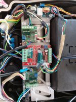
I already test this driver (20 or 30 hours mowing) for drive motor inside a very small YARDFORCE mower ,It work well but power is very low and driver freeze very often on high grass.
1743364995111.jpeg
I finally replace them by ZSX11H and mower never freeze again.
Adjusting the sense in the firmware don't help certainly driver react faster.

ZSX11H work perfectly at normal or high speed in all my test with TEENSYBER to control a perfect straight lane (15ms motor control loop) ,so maybe a serialrobot driver speed adjustement control.


Take care to this :
Everything work perfect if you have a positive torque on the motor (accelerate) ,but if one wheel have to reduce his speed and not the other one ,you need to use the brake feature or it can't work.
 
freeze is error and stop to drive the motor.
It's append each time sense is too high , you have the same error on ZSX11 , but at higher sense.
Unfortunately when i try to post code or join video, forum crash and i can't have access to site for next 2 or 3 days :unsure:
You need to send a pwm value to brake pin to perfectly control speed when negative torque is apply to motor (bottle raise down).
Easy to say and complex to write .
 
You need to send a pwm value to brake pin to perfectly control speed when negative torque is apply to motor (bottle raise down).
oh, would be nice, if you could share the code. I'am very intrested in. The problem with the break was the reason, why I changed to brushed motors. My yard has a lot of ups and downs so that my robot lost his way all the time with brushless motors.
 
I‘m currently writing motor control code for pico. There is also break input PWM controlled in case of negative torque. At the moment sunray fw sends controlled PWM set points to pico. My plan is to move Motor control to pico. In this case sunray fw will send linear and angular speed setpoints to pico and pico will generate controlled PWM signals
 
If you stay on Ardumower platform and the sunray code is running on due or agm4 is C++ maybe the best way. If you go to Alfred platform and use raspberry pi as a main unit and for low level stuff a bare metal cpu like pico is micropython also a way. My work is posted here
https://github.com/EinEinfach/Sunray
You have to switch to Landrumower-Linux branch. In the folder Landrumower you’ll find the firmware code for pico (micropython). But I still didn’t commit anything related to pid control, but I think in the next days I will upload something
 
the plan is to remove the agm4 and do the low level stuff on Pico and the other things on RPI. In best case, its a Zero2, otherwise I have to switch to 4 or 5.
Can't wait for your code...
 
Code for bottle movement on the video arduino mega and ZSX12
Code:
//test on ZS-X12H


#define pinOdometry 2

#define pinMotorPWM 9
#define pinMotorBRK 10
#define pinMotorDIR 11

int odo_cible = 0;    //
int motor_speed = 30;  // from 0 to 255
int motor_brake_power = 50;
unsigned long odoLeft = 5000;
int odometryTicksPerRevolution = 510;

boolean usebrake = false;
boolean run_CCW = false;
boolean motor_stop =false;
unsigned long nextTimeOdometry ;
unsigned long lastMotorRpmTime ;
float odometryTicksPerCm ;  // encoder ticks per cm
float motorLeftRpmCurr ; // left wheel rpm
float motorLeftSpeedRpmSet ; // left wheel rpm


void setup() {
  motorLeftSpeedRpmSet = 30.0 ;
  odometryTicksPerCm = 22 ; // encoder ticks per cm
  nextTimeOdometry = millis(); ;
  Serial.begin(115200);
  Serial.println("Motor Test");
  //analogWriteFreq(10000);
  pinMode(pinMotorDIR, OUTPUT);
  digitalWrite(pinMotorDIR, HIGH);
  pinMode(pinMotorPWM, OUTPUT);
  pinMode(pinMotorBRK, OUTPUT);
  analogWrite(pinMotorPWM, 0);
  pinMode(pinOdometry, INPUT);   //plus/Hall sensor detection - Count steps
  attachInterrupt(digitalPinToInterrupt(pinOdometry), plus, RISING);

  int myEraser = 7; // this is 111 in binary and is used as an eraser
  TCCR2B &= ~myEraser; // this operation (AND plus NOT), set the three bits in TCCR2B to 0
  int myPrescaler = 2; // 1=31Khz 2=4Khz
  TCCR2B |= myPrescaler;
  delay(3000);

}

void plus() {
  if (run_CCW) {
    if (motor_stop){
      odoLeft--; //count steps
    }
    else{
      odoLeft++; //count steps
    }
    
  }
  else {
    odoLeft--; //count steps
  }

}


// calculate map position by odometry sensors
void calcOdometry() {

  if (millis() < nextTimeOdometry) return;
  nextTimeOdometry = millis() + 100; //bb 300 at the original but test less
  static int lastOdoLeft = 0;
  int ticksLeft = odoLeft - lastOdoLeft;
  lastOdoLeft = odoLeft;

  double left_cm = ((double)ticksLeft) / ((double)odometryTicksPerCm);

  motorLeftRpmCurr  = abs(double ((( ((double)ticksLeft) / ((double)odometryTicksPerRevolution)) / ((double)(millis() - lastMotorRpmTime))) * 60000.0));
  lastMotorRpmTime = millis();

  if (run_CCW) {
    if ((motorLeftRpmCurr) < motorLeftSpeedRpmSet) {
      motor_speed = motor_speed + 2;
    }
    else {
      motor_speed = motor_speed - 2;
    }
  }
  else {
    if ((motorLeftRpmCurr) < motorLeftSpeedRpmSet) {
      motor_speed = motor_speed + 2;
      motor_brake_power = motor_brake_power - 2;
      if (motor_brake_power<0) motor_brake_power=0;
    }
    else {
      motor_speed = motor_speed - 2;
      motor_brake_power = motor_brake_power + 2;

    }
    
    if (motor_speed < 0) {
    
      //digitalWrite(pinMotorBRK, LOW); //no brake
      analogWrite(pinMotorBRK, motor_brake_power); //faster in load
    }
    else{
     // analogWrite(pinMotorBRK, HIGH); //faster in load
      analogWrite(pinMotorPWM, abs(motor_speed)); //faster in load

    }
  }


}


void loop() {

  //on monte
  motor_speed = 70;  // from 0 to 1024
  motor_stop=false;
  run_CCW = true;
  //Serial.print("On monte init : ");
  //Serial.println(odoLeft);
  odo_cible = 5500;
  //odo_cible = odoLeft + odometryTicksPerRevolution;
  digitalWrite(pinMotorBRK, HIGH); //no brake
  digitalWrite(pinMotorDIR, HIGH);
  analogWrite(pinMotorPWM, motor_speed); //faster in load

  while  (odoLeft < odo_cible) {
    calcOdometry();

    analogWrite(pinMotorPWM, motor_speed); //faster in load
    Serial.print(motor_brake_power);
    Serial.print(",");
    Serial.print(motor_speed);
    Serial.print(",");
    Serial.print(motorLeftRpmCurr);
    Serial.print(",");
    Serial.print(odoLeft);
    Serial.println();
  }
  analogWrite(pinMotorPWM, 0); //stop
  digitalWrite(pinMotorBRK, LOW); // brake
  motor_stop=true;
  delay(2500);


  //on descend
  motor_speed = 3;  // from 0 to 1024
  motor_brake_power=70;
  motor_stop=false;
  //Serial.print("On descend : ");
  //Serial.println(odoLeft);
  odo_cible = 5000;
  //odo_cible = odoLeft - odometryTicksPerRevolution;
  run_CCW = false;
  digitalWrite(pinMotorBRK, HIGH); //no brake
  digitalWrite(pinMotorDIR, LOW);
  analogWrite(pinMotorPWM, motor_speed); //faster in load

  while  (odoLeft >= odo_cible) {
    calcOdometry();
    analogWrite(pinMotorPWM, abs(motor_speed)); //faster in load

    Serial.print(motor_brake_power);
    Serial.print(",");
    Serial.print(motor_speed);
    Serial.print(",");
    Serial.print(motorLeftRpmCurr);
    Serial.print(",");
    Serial.print(odoLeft);
    Serial.println();
  }
  analogWrite(pinMotorPWM, 0); //stop
  digitalWrite(pinMotorBRK, LOW); // brake
  motor_stop=true;
  delay(2500);

}
 
If you clone the landrumower-Linux repository it is already work fine and you can use it with pico fw, there are also schematics how to connect motors bumpers etc. It is more or less Alfred but instead of ngp board pico is used
I am on the way. But due to speed-limitation of micropython I try to write the FW in cpp. I think thats realy relevant for fast and responsive PID-cycles.
My goal is to use your PCB and drive with my cpp-FW.
Did you test Bernards code with your micropython FW?
 
It’s really funny but I end my micropython experience with the same results… all try’s to optimize code and make it faster are failed, especially with using PID on pico. I stopped the development on ver 2.x and rewrite the whole code in cpp. The version 3.x :) The first results are awesome comparing to speed performance. I have round about 50000 loops/s in cpp comparing to 20 in micropython :)
 
Du musst aufpassen da läuft noch nichts vernünftig, Gear Motoren machen komische Sachen, ich vermute der LoopCall kommt zu schnell hintereinander, Mähmotor dreht gut. Shutdown ungetestet, Spannung-Strommessung funktioniert gut, Buzzer piept irgendwie nicht mehr, hat aber schon mal funktioniert
 
Oben