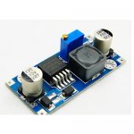
sender area 2

andri85

Member
Hello
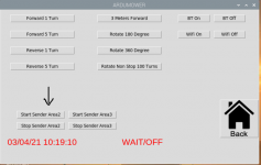
i made the sender to cut in area 2 but i can't get it to communicate with the robot. Through the browser the sender turns on and off, when I do the test through Piardu it returns me SENDER FAIL. The sender for area 1 use that of marotronics. On the console, doing the start from Piardu, I saw that it returns the ip address 192.168.1.172/A1, turning on via the browser instead gives the command 192.168.1.172/1, can it be that A that makes the wrong operation do?
thanks
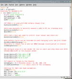
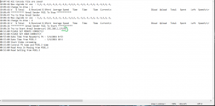
Config.py.PNGconsolle.PNGimmagine pi ardu.PNGparametri arduino esp.PNG

image0.jpeg
 
thanks
now works
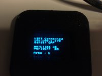
but what is the second loop for? I saw that when I press on start area 2 on the display SENDER A is written
 
The L298N have 2 output A and B ,so it's possible to use 2 perimeters wires with the same sender.
Useful on really particular config area
But code have to be adjust.
 
Ah OK. I also saw that there is the scheme to make the sender with the door.
Does the code provide for it or does it need to be changed?
 
Hi Bernard
this weekend I started it, but it gives me some problems that I have been carrying around since last year. I tried to fix it by changing RTC but I still have problems.
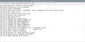
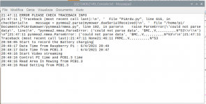
Randomly I get a TRACEBACK error, then when I restart PIARDU sometimes I get the RTC error on i2c. I reboot raspberry and arduino and everything is solved. What is it that I could check?
errore traceback.PNGrtc.PNG
 
For RTC issue : What is connected over I2C to PCB1.3 ?
Try to increase the watchdog delay into robot.cpp near line 2000 (test with 30000).

For traceback, It's append when serial connection between DUE and PI is broken. (2 possibility : DUE reset by watchdog or PI freeze for more than 5 seconds).
When watchdog is set to 30000 ,normally this never append on DUE side,or you have a big RTC or IMU issue.

For raspberry you need to check that PI have a correct WIFI (very important on startup) and never disconnect or reconnect on different acces point while mowing for long duration.

In the past i try to manage the Serial com in a new thread, maybe it's the solution to avoid that Piardu freeze.
 
On i2c there is connected the RTC and 2 imu. There are 2 IMUs because last year I found the GY88 with the mmc5883 compass, then I connected a second IMU that had the HMC5883 compass, I removed the peripherals that did not need the second IMU from the pcb. In the raspberry this year I put an external alpha wifi antenna, so I don't think there are disconnections. Tomorrow I try to change the watcdog.
 
I forgot last year I had to connect both the RTC and the IMU on other ports because both level converters burned by themselves
 
2 IMU ?? be careful that they don't have same I2C address or same as RTC.
It's better to test with only GY-88 with MMC5883 and deactivate compass in arduremote setting IMU for 2or 3 days with long duration mowing.

I check code and try to add support for MMC5883 , but without one it's certainly a little complex to test.
 
no they don't have the same address. I have already checked, however I try to disconnect the compass and navigate without it, let's see if it still gives me any problems
 
I set the watchdog to 30000. Now the robot is on the table in the laboratory stopped in charge and I have a TRACEBACK error again.
But it gives different information

errore traceback 2.PNG
 
I set the watchdog to 30000. Now the robot is on the table in the laboratory stopped in charge and I have a TRACEBACK error again.
But it gives different information

Anhang anzeigen 1829
YES test a new USB cable
Something is very strange because $MC,,V is totaly wrong .
If possible you can connect a monitor on HDMI to check is the power supply of PI is OK (If not a yellow star is present on upper right and i am not sure that you can see it over VNC)

How did you power the PI (DC/DC power ?????)
 
Oben