I'm building my Mower, and I'm having trouble with the perimeter receiver losing signal in the middle of my lawn.
Using the Azurit software, I'm seeing smag <300 when the ArduMower is only 3-5 meters from the perimeter at times. (I was expecting much longer range possible).
I'm planning on trying the Raindancer software this week, but before I try other software, I wanted to know whether my hardware choices were correct.
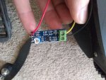
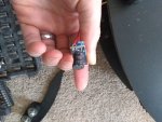
I wired my receiver as follows:
- Coil directly to PCB
- Ground/signal to the terminal blocks
- VCC only to the head of the chip.


Some of my confusion is that:
- This page shows that I should split the ground wire to be on both ends of the PCB
- This thread indicates that the split ground is NOT necessary.
Does anyone have experience with the split/not-split ground? should I modify my receiver?
Thank you
Using the Azurit software, I'm seeing smag <300 when the ArduMower is only 3-5 meters from the perimeter at times. (I was expecting much longer range possible).
I'm planning on trying the Raindancer software this week, but before I try other software, I wanted to know whether my hardware choices were correct.
I wired my receiver as follows:
- Coil directly to PCB
- Ground/signal to the terminal blocks
- VCC only to the head of the chip.


Some of my confusion is that:
- This page shows that I should split the ground wire to be on both ends of the PCB
- This thread indicates that the split ground is NOT necessary.
Does anyone have experience with the split/not-split ground? should I modify my receiver?
Thank you