Du verwendest einen veralteten Browser. Es ist möglich, dass diese oder andere Websites nicht korrekt angezeigt werden.
Du solltest ein Upgrade durchführen oder einen alternativen Browser verwenden.
Du solltest ein Upgrade durchführen oder einen alternativen Browser verwenden.
Perimeter sender/receiver few questions
- Ersteller alda
- Erstellt am
Sending picture of receiver :

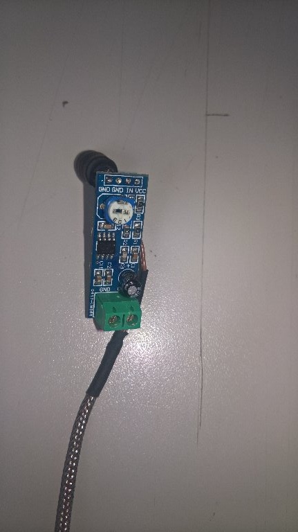

Coil type is correct.
Attachment: https://forum.ardumower.de/data/media/kunena/attachments/1183/WP_20170530_07_18_06_Rich.jpg/
Coil type is correct.
Attachment: https://forum.ardumower.de/data/media/kunena/attachments/1183/WP_20170530_07_18_06_Rich.jpg/
Zuletzt bearbeitet von einem Moderator:
So I did next test with osci :
What I'm receiving when I have only coil without amplifier :


Received signal is symetric about 0V.
Now with amplifier and sender switched off :

stable mean value 2,55V
and with amplifier and sender on :

also symetric, but mean value is 2,45V
Here I see first problem, that mean value with sender on/off is different (2,55/2,45). It's 0,1V.
But I can say, that sender and receiver is working correctly.
Now I must think, how to adjust ADC to have correct mean value. If I have ADC value 518 it's aprox 2,53V but I think for correct working I need manualy adjust this value to 2,45V = 502.
Or what's your opinion ?
Attachment: https://forum.ardumower.de/data/media/kunena/attachments/1183/WP_20170530_09_35_20_Rich.jpg/
What I'm receiving when I have only coil without amplifier :
Received signal is symetric about 0V.
Now with amplifier and sender switched off :
stable mean value 2,55V
and with amplifier and sender on :
also symetric, but mean value is 2,45V
Here I see first problem, that mean value with sender on/off is different (2,55/2,45). It's 0,1V.
But I can say, that sender and receiver is working correctly.
Now I must think, how to adjust ADC to have correct mean value. If I have ADC value 518 it's aprox 2,53V but I think for correct working I need manualy adjust this value to 2,45V = 502.
Or what's your opinion ?
Attachment: https://forum.ardumower.de/data/media/kunena/attachments/1183/WP_20170530_09_35_20_Rich.jpg/
Zuletzt bearbeitet von einem Moderator:
Hi.
Yes it's very Strange.
Have you compared the scope on the output of receiver in the 3 position IN OUT and upper the Wire.
Have you try to make a factory setting and new ADC to be sure ?
If you want i can make a scope on my receiver to be sure but normaly your result is good.
By.
Yes it's very Strange.
Have you compared the scope on the output of receiver in the 3 position IN OUT and upper the Wire.
Have you try to make a factory setting and new ADC to be sure ?
If you want i can make a scope on my receiver to be sure but normaly your result is good.
By.
Hi
Here the plot.
On the wire

IN
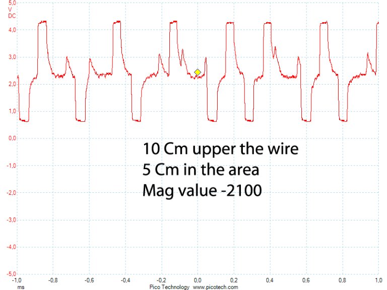
and OUT

By
Attachment: https://forum.ardumower.de/data/media/kunena/attachments/3545/receiverIN.jpg/
Here the plot.
On the wire
IN
and OUT
By
Attachment: https://forum.ardumower.de/data/media/kunena/attachments/3545/receiverIN.jpg/
Zuletzt bearbeitet von einem Moderator:
Hi,
I did again tests on my garden and now perimeter detection is working very good")
But on the start of perimeter tracking is mower very much oscilating around perimeter ... I think I must adjust PID (but not sure if P or I or D) .... and also I must improve wheels, because they slip on the hill.
Alex
I did again tests on my garden and now perimeter detection is working very good
But on the start of perimeter tracking is mower very much oscilating around perimeter ... I think I must adjust PID (but not sure if P or I or D) .... and also I must improve wheels, because they slip on the hill.
Alex
Hi Roland
Ok with alda , why did you say signal too strong .
Max value is under 5v and min up to 0v
But for me, i read a lot of post on the mag value and it is very difficult to understand.
For example if you look at the scope in or out there are praticly the same so how the code detect the sign of mag
The main is that it's work perfectly for me.
Thanks
Because off the signal shape. It is a square. The amplifier goes in saturation and is not able to go to signal zero (2.5V) while a new flank is comming.
This means, a small peak makes a square.
"Max value is under 5v and min up to 0v"
In order VCC is 5V the Signal will never go above this.
This means, a small peak makes a square.
"Max value is under 5v and min up to 0v"
In order VCC is 5V the Signal will never go above this.
No, thats not the way it works. The signal will be sampled 2 periods long and then compared in a crosscorrelation to a saved signal. The amplitude of the crosscorrelation determin if you get 1 or -1.
Maybe you search for matched filter.
Here is a video - but in german. https://www.youtube.com/watch?v=NIer_kITelc&t=2s
My signal is like yours, but not complete saturated. If it works, its ok. But you can get problems, if the saturation is too high. You will realise this first, when the mower have a strange behaviour near the perimeter.

Attachment: https://forum.ardumower.de/data/media/kunena/attachments/2936/IMG_0308_2017-06-01.JPG/
Maybe you search for matched filter.
Here is a video - but in german. https://www.youtube.com/watch?v=NIer_kITelc&t=2s
My signal is like yours, but not complete saturated. If it works, its ok. But you can get problems, if the saturation is too high. You will realise this first, when the mower have a strange behaviour near the perimeter.
Attachment: https://forum.ardumower.de/data/media/kunena/attachments/2936/IMG_0308_2017-06-01.JPG/
Zuletzt bearbeitet von einem Moderator:
For me it's clear. Perimeter detection is working very good, but I still have a problem with perimeter tracking. Critical problem is on the start of tracking. Mower is very oscilating around wire and sometimes will start turning. When mower is already on the wire, oscilation is much lower. I think, that problem is PID setup, but there isn't clear guide how setup PID. I don't know if increase/decrease P or I or D.
Alex
Alex
Hi Roland.
Thanks for this video but in german so it's difficult but i think with subtitle i understand the main.
In fact what is strange and magic for me
I think we use the useDifferentialPerimeterSignal = true In perimeter.cpp
int8_t sigcode_diff[] = { 1,0,-1, 0,1,-1,1,-1, 0,1,-1,1,0,-1, 0,1,-1, 0,1,-1, 0,1,0,-1 };
And if you read your perfect scope
it's (0,-1,1,-1,0,1,-1,1,0,-1)
my bad scope (in fact i realise that my tianchen mower perimeter was on and is also read by the receiver ,the small pic you can see.,i try to make a new record)
it's (-1,0,1,-1,0,1,0,-1,1,0,-1,0,1,-1,1,-1,0,1,-1) outside
it's (-1,1,0,-1,0,1,-1,0,1,0,-1,1,-1,1,0,-1,1,-1,0) inside
The alda scope
it's (1,-1,0,1,-1,1,0,-1,0,1,-1,0,1,-1,0,1,0,-1,0,1,-1)
And none of these 4 scope match perfectly the sigcode_diff
But as the perimeter is perfecly detect i thing the correlation match filter work well.
When you say
Your signal is really perfect did you use the sender, coil and receiver from ardumower ?
Again thanks for your explaanation.
Thanks for this video but in german so it's difficult but i think with subtitle i understand the main.
In fact what is strange and magic for me
I think we use the useDifferentialPerimeterSignal = true In perimeter.cpp
int8_t sigcode_diff[] = { 1,0,-1, 0,1,-1,1,-1, 0,1,-1,1,0,-1, 0,1,-1, 0,1,-1, 0,1,0,-1 };
And if you read your perfect scope
it's (0,-1,1,-1,0,1,-1,1,0,-1)
my bad scope (in fact i realise that my tianchen mower perimeter was on and is also read by the receiver ,the small pic you can see.,i try to make a new record)
it's (-1,0,1,-1,0,1,0,-1,1,0,-1,0,1,-1,1,-1,0,1,-1) outside
it's (-1,1,0,-1,0,1,-1,0,1,0,-1,1,-1,1,0,-1,1,-1,0) inside
The alda scope
it's (1,-1,0,1,-1,1,0,-1,0,1,-1,0,1,-1,0,1,0,-1,0,1,-1)
And none of these 4 scope match perfectly the sigcode_diff
But as the perimeter is perfecly detect i thing the correlation match filter work well.
When you say
i don't understand this ?The signal will be sampled 2 periods long
Your signal is really perfect did you use the sender, coil and receiver from ardumower ?
Again thanks for your explaanation.
Hello Bernard,
I use another signal, which is 60 signs long. You can't compare it with the original Ardumower signal.
When your perimeter is perfecly detect then its fine. Normally in the garden the magnetic field is not as strong as when one test it in the house.
the matched filter searches for on signal in another signal. for example:

So we go through the sampled array and look on each position, if the signal is there.
It could be, that the sampling begin in the middle of the signal but we need the whole signal in one peace to find it.
Therefore the signal what is sampled from the perimeter must be twice as long as the sigcode_diff in order to find it because it must stand in the array in one piece.
Hope that helps.
Attachment: https://forum.ardumower.de/data/media/kunena/attachments/2936/Unbenannt_2017-06-02.png/
I use another signal, which is 60 signs long. You can't compare it with the original Ardumower signal.
When your perimeter is perfecly detect then its fine. Normally in the garden the magnetic field is not as strong as when one test it in the house.
the matched filter searches for on signal in another signal. for example:
So we go through the sampled array and look on each position, if the signal is there.
It could be, that the sampling begin in the middle of the signal but we need the whole signal in one peace to find it.
Therefore the signal what is sampled from the perimeter must be twice as long as the sigcode_diff in order to find it because it must stand in the array in one piece.
Hope that helps.
Attachment: https://forum.ardumower.de/data/media/kunena/attachments/2936/Unbenannt_2017-06-02.png/
Zuletzt bearbeitet von einem Moderator:
Hi Roland
Thanks a lot .
I follows all the ardumower post and view that you help a lot of membre (I use a Due and the ADCman in background and it work very well).
I read some paper on the nucleo board and remark that a ST-Link debugger/programmer is include in the board.
Does it mean that you can view the value of all variable in real time into a console and put some breakpoint,or you need like in arduino to change and
recompile the prog each time you need to view the value of specific variable (by adding a Console.print ....).
I view on the net this GPS
https://drotek.com/tiny-rtk-u-blox-neo-m8p/
The accuraty is 2.5CM
Do you think it's possible, because with this accuraty the wire and perimeter are not necessary .
Maybe a member know this GPS ?
By.
The debugging of the nucleo depends of the IDE. For my perimeter receiver I used System Workbench for STM32 for creating the code and have a debugger included. For my controller Nucleo I uses mbed and here I have to do it Arduino like.
Regarding GPS I never dealed with it. It sounds good, but as I remembered, the GPS signal will not be sent as precisely, as that you can determine cm. Maybe only for military or commercial paying users.
Regarding GPS I never dealed with it. It sounds good, but as I remembered, the GPS signal will not be sent as precisely, as that you can determine cm. Maybe only for military or commercial paying users.