PCB 1.3 und Raspberry

paddy

Active member
Hallo zusammen,

im Wiki habe ich ein Bild vom PCB 1.3 gesehen, auf dem eine Raspberry Schnittstelle eingezeichnet ist. Dazu konnte ich aber nichts genaueres finden. Was ist denn hier implementiert? Kann ich hierüber einen Raspberry versorgen und kontrolliert herunterfahren (Notaus) oder soll hier eine Kommunikation zwischen DUE und Raspberry (USB native Port?) realisiert werden?
 
Hi all
I also want to connect a Raspberry on the PCB1.3 but need some clarification about the POWER Line:

When i build the PCB i don't understand the utility of EF3 and why it's locate on the 24V line, instead of the 9V (at the out of U1) ????
If i correctly understand the board we can't directly connect the PI and need to add another DC/DC converter connected at P16 to powered the PI ?
So why EF3 P16 etc... certainly i have misunderstood Something ?

@Paddy
USB native port to RPI work to flash the DUE so normaly it can work to communicate.
You can find a complete thread about this on the forum.

By.
 
Hi UWE.
Thanks for the link.
I read a thread about this, but with Google translate it's really not clear and i don't understand the utility of this board (I2C and RTC etc....).

Can you explain in English if possible or with simple world the main feature and utility of this board ?

Why do not simply plug the PI at the 9V of PCB1.3 and use the USBNative port to exchange data ?

Many thanks.
 
Hallo
Die Platine ist eigentlich eine Entwicklung von Jürgen.
Ich versuche es mal mit meinen Englisch Kenntnissen.
Das Hauptproblem ist beim Rasperry das dieser beim Ausschalten evl noch Daten auf die SD Karte schreib will was er aber nicht kann weil die Spannung plötzlich fehlt.
Diese Platine soll das verhindern.

"Sobald Power Source Stromlos ist erkennt das die Schaltung der Pi wird jetzt über Power-Backup versorgt. Power-Backup wird dann auch vom Akku getrennt wenn der Pi runtergefahren ist.
Damit kann der Rasperry herunterfahren und alle Daten auf der SD Karte schreiben und schaltet sich danach selber ab.
Hier ist der Link zu Jürgen seiner Seite wo er die Platine vorstellt.

Hello
The board is actually a development of Jürgen.
I'll try my English skills.
The main problem is the Rasperry that this when switching evl still want to write data on the SD card but what he can not because the voltage is suddenly missing.
This board should prevent this.

"As soon as the power source is de-energized, the Pi's power supply is now powered by power backup, and power backup will be disconnected from the battery once the Pi has shut down.
This allows the Rasperry to shut down and write all data to the SD card and then turn itself off.
Here is the link to Jürgen his page where he presents the board.
http://www.ardumower.de/index.php/de/forum/andere-projekte/1111-raspberry-pi-2-3-power-switch#11118
Gruß
Uwe
 
Hi Uwe.
To power the PI.
I have tested this part : https://www.modmypi.com/raspberry-pi/power-1051/ups-boards-1051/ups-pico on my PI and the result is OK on the table (When i disconnect the power the UPS wait 1 minute and shutdown the PI , when the power is back the PI start again and the small battery is charging)
Simply need to confirm into the mower.

I also test this one http://www.dx.com/p/power-supply-expansion-board-for-raspberry-pi-3-model-b-blue-456390#.WmjeAExFz5A but here the powering and charging is more complexe and require other PCB
I have a new question
Do you thing it's possible to power the RPI 3 with the 5V of the PCB1.3 or it's better to add a new DC/DC convertor from 24 to 5 Volt
And if i want that the PI is disconnected by the undervoltage protection on PCB1.3 , where can i find a connector (P16 and P17 are not undervoltage protected if i understand correctly).

Many thanks.


Thanks.
 
Hi Bernard,

what make you think you need additional PCBs for the second solution you provided? As I see from description, it seems to have everything on board like lithium charger also the DCDC converter to output 5V. I've seem some powerbanks to charge smartphones out there which can be charged and discharged at same time. I'm wondering if we can use such a device. Some of them are suitable to power a PI (taken from review). Most of them seems to stop power the device for a short period (few ms) when switch charging states. This is an issue as PI crashes at this moment. Maybe this can be solved by some capacitors.

There is a powerbank from Intenso (https://www.amazon.de/Intenso-Powerbank-Ladeger%C3%A4t-Smartphone-Digitalkamera-schwarz/dp/B015CIZEF0/ref=sr_1_1?ie=UTF8&qid=1516862436&sr=8-1&keywords=intenso+powerbank+10000) which seems to work. You don't need to push buttons, no auto shutoff or other things. Maybe I try it out. I want to attach the charging input to charging pins of mower directly (sure, a DCDC converter is needed). During mow, PI gets powered by powerbank only. I'm not sure how this influence the overall charging process of mower. Because the power supply also powers base station and PCB does cut battery if full charged, it should work in my opinion.

Main issue I see with connecting to PCB directly is undervoltage circuit and emergency-stop button. Both will disconnect PCB from battery, so PI will always crash without additional power source (like power backup attached to battery)

Patrick
 
Hi Paddy
what make you think you need additional PCBs for the second solution you provided?
When i test the second solution the battery did not charge while power the PI.
If the switch is ON the PI is powered but the charging circuit is disconnected.
If OFF the PI is not powered and the battery is charging.
So it can't work like that.

Main issue I see with connecting to PCB directly is undervoltage circuit and emergency-stop button. Both will disconnect PCB from battery
It's why the first solution is perfect (except the cost).
If the mower is stuck for a long time the 24V bat come low , the undervoltage disconnect the power and the UPS wait a minute and stop correctly the PI.
So all is OFF .
When you put back the mower into the station the 24V restart the PI and when you start the mower(Push Button) the DUE restore the serial communication.(But not sure because i have Tested only on table so need to confirm into the mower).

By.
 
Hi All
Today it's not rain :)
So the first test outdoor with the PI Command.
The soft run into Raspberry and I have acces with VNC or other SSH+X11 soft on many platform.
Here it's with my PC with Mobaxterm
The connection to the PCB 1.3 is at P16 (24V RPI Backup)
implant.jpg

And here a short video of the test the only issue (and not the easier to solve) is that the WIFI direct connection for camera and remote is only good at less than 5 Ml but no problem because all is working into the PI and the PC is only here as interface. https://youtu.be/lRnBLLbOhsA Nothing is finish but the reaction time is perfect.
Attachment: https://forum.ardumower.de/data/media/kunena/attachments/3545/implant.jpg/
 
Zuletzt bearbeitet von einem Moderator:
Hello Bernard,
that's a nice solution. I like the software for the PI. Looks very good.
Which ArduMower firmware do you use. Is that also compatible with AZURIT 7A?
Something worries me about the USB connection. If the Main 1.3 is turned off and the PI stays on, the Main will be powered by the PI, which will cause problems. Have you already had experience with it?

Regards Jürgen
 
Hi Jurgen.
Very good remark.
Yes there is a problem with the power and don't know exactly if Dangerous or not and how to solve it.
When i unplug the power on the PCB1.3 the PICO UPS continue to power the PI and the DUE via The serial USB during 1 Minutes ,Do You think there is a risk ?.
The other issue is that when i power again the PCB the DUE is also powered via serialUSB and start immediatly the 24V without need of powerbutton.

The USB line is GND 5V and 2 Data, Is it possible to simply cut the 5V and GND without stopping the serial exchange (maybe yes if data line is optocouple on PI and DUE but i am not sure)???.

I read a lot on the power switch but want to find a simple solution to shut down correctly the PI The PICO UPS work very well in this

For the Ardumower Firmware i use my own version with Odometry mandatory but it's based on 1.07 azurit and all the data exchange use a new class , so it's certainly easy to adapt it on AZURIT based firmware.

Actualy (The add of the PI is only gadget and fun), i use it only to record all the data for a long duration to check all my change into firmware.
But the main futur process is to use the PI for GPS Mapping and select area mowing.
I think the Vision Kit of Google need to be explore Also.
 
Hi Bernard,
the risk with the power supply via USB is not to be underestimated. There are several aspects here. The worst thing that can happen is the defect of the USB interfaces. There are several solutions here.
1. Opto-galvanic isolation of the USB interface.
2. Ensuring startup and shutdown sequences.
The PI Power ++ PCB fulfills the second point. It is very "big" but it should be only an addition with additional possibilities to influence the ArduMower. With your solution I would put on point one. These modules are ready to buy and are very easy to handle.

Hi Bernard,
das Risiko mit der Spannungsversorgung über USB ist nicht zu unterschätzen. Es gibit hier gleich mehere Aspekte. Das schlimmste was passieren kann ist der Defekt der USB Schnittstellen. Es gibt hier mehrere Lösungen.
1. Optogalvanische Trennung der USB Schnittstelle.
2. Die Sicherstellung der Start und Abschalt- Sequenzen.
Das PI Power ++ PCB erfüllt den zweiten Punkt. Es ist zwar sehr "groß" aber es sollte ja nur ein Zusatz sein mit zusätzlichen Möglichkeiten auf den ArduMower einzuwirken. Bei Deiner Lösung würde ich auf Punkt eins setzen. Diese Module gibt es fertig zu kaufen und sind sehr einfach zu handhaben.
https://www.ebay.de/i/232469730087?chn=ps&dispItem=1 https://www.reichelt.de/?ARTICLE=15...V59mYxiMBTABKIzW-_aIYmeg5lq9eHaYaAj31EALw_wcB https://www.reichelt.de/ICs-ADC-ADX...nr=ADUM+3160&SEARCH=USB+Isolator&trstct=pos_1
I have not tested these components yet.
 
Hallo,

ich habe mich nochmal mit dem PI beschäftigt und hier einen Vorschlag, den ich gerne mit euch diskutieren würde.

Ich verwende einen Orange PI Zero, einfach weil ich den hier habe. Dieser hat wie der Raspberry einige GPIOs und liefert auch an einigen Pins eine feste Spannung (5V und 3,3V).

Meine Idee ist, den PI Switch von Jürgen auf das wesentliche zu beschränken. Der PI soll nur herunterfahren, sonst nichts. Beim testen habe ich festgestellt, dass der 3,3V Pin nach dem abschalten nur noch 0,7V liefert. Die 5V Pins liefern weiterhin 5V.

Daraus ist folgende Idee entstanden:

Über eine kleine Lochrasterplatine werden zwei Mosfets an die Batterie angeschlossen. Einer wird durch 3,3V vom PCB geschaltet. Damit wird der DC/DC Wandler versorgt und schaltet den PI an. Dieser schaltet den zweiten Mosfet ebenfalls mit dem 3,3V Pin.
Zudem gibt es eine Verbindung zwischen den 3,3V des PCB zu einem der GPIO vom PI.

IMG_20180413_112346.jpg

Wenn das PCB nun abgeschaltet wird (oder sich selbst abschaltet), fallen die 3,3V vom PCB aus. Der erste Mosfet öffnet, die Schaltung wird über den zweiten aber gehalten. Der PI registriert, dass der GPIO auf Low geht und initiiert den Shutdown. Ist dieser abgeschlossen, fällt der 3,3V Pin vom PI auf 0,7 und der zweite Mosfet trennt die gesamte Schaltung von der Batterie.

Nun die Frage an die Experten, klappt das so? Ich habe einige IRLIZ44N herum liegen, kann ich die dafür verwenden? Passen die Widerstände, um das Gate auf GND zu ziehen? Irgendwas vergessen?

Damit der Arduino und der PI sich nicht über USB versorgen, würde ich dann einen dieser Isolatoren verwenden. Wie ist das denn auf der Platine von Jürgen gelöst?

Viele Grüße
Patrick
Attachment: https://forum.ardumower.de/data/media/kunena/attachments/2946/IMG_20180413_112346.jpg/
 
Zuletzt bearbeitet von einem Moderator:
Hi Jurgen.
I have tested the first module ordered on EBAY
but unfortunatly it didn't work with the PI, the Serial connection work for 1 seconde and freeze the Pi after , i tested with different speed etc and it never work.
But it work perfectly between the PC and DUE at 115200 Bds so the module is OK.

In fact what is exactly the risk of the USB, on shutdown mode, or during the working condition ?

I have all working into the mower for more than 10 Hours and with 5 or 6 full shutdown without issue but ?????

The new PICO UPS can be powered directly with 24V cc so now it's possible to have a complete easy working solution for PI.

By.
 
Hi Paddy.

If you don't want to use a Strompi2 or Pico UPS maybe you can test your solution but:

The most simpliest solution is to use other switch for the PI
Battery ->Switch1-> PI
Battery ->Switch2-> PCB1.3

Now the normal shutdown use the Switch2 ,using 3.3V from the PCB to one PI GPIO PIN initiate the safety shutdown of the PI
The very low electrical consumption of the pi ZERO in sleep mode is not a problem for many days or week on mower Battery.

You can now use Switch 1 to restart the PI or disconnect all.

Maybe a strompi2 can work with PI ZERO.

By.
 
Bernard
The issue with Pi and mower is not boot up and shutdown by button.

The real issue is that Pi will still draw power If mower gets turned off. Especially If mower turns off because it stucks or if battery is low and charging station can't get reached fast enough. In this cases, the mower turns off to save battery life. But if pi still runs it will draw battery to dead.
Therefore Pi must recognise if mower is operational and shutdown if not.
This can't be solved by buttons
 
Hi Paddy.
I tell you this only a low cost alternative solution ;)
PI and DUE same Power management is not really easy.

We need to make the difference between PI shutdown and PI power OFF.
And know the electrical consumption of the pi ZERO.

The very low electrical consumption of the pi ZERO in sleep mode is not a problem for many days or week on mower Battery.

So if a problem occur on the mower the PIN4(RelaisAbschaltung) can initiate the power off of the PCB1.3 and the safety shutdown of the PI ( simply check the there is 24V on P16 or not, using PI GPIO)
Now i think you certainly have more than one day to find your mower stuck and manualy power OFF the PI (Also,normaly Li ION battery are already undervoltage protected)


In this cases, the mower turns off to save battery life. But if pi still runs it will draw battery to dead

The UPS Pico stop completly the POWER on the PI (Actualy i have connected it on P17 but i can again test on P16) so normaly undervoltage or stuck can Power OFF all.
The next time i open the mower i try to make the change to test and if it's works a small video.

If i remember well when i have plug the PI on P16 the Pico power again the PCB by reverse across the DC/DC with his small battery :oops: :oops: so i stop this and prefer to use P17.

By.
 
Hi Paddy.

Finally i find a good working solution without any UPS, only the PI and the soft ;) .
The Pi is connected on P17 so it is powered after the undervoltage protection , JP8 need to be in Autom position

Now the mower is only start with pushbutton and stop with a command into PFOD or by the undervoltage protection.

Into the DUE Azurit send a command to the PI to tell it to shutdown (so the soft into the PI start the safety shutdown and the USB power is OFF also,it was the main issue i have in the past because the USB can power again the DUE if all is turn off at the same time).
After a delay of 1 minute the DUE Power off the PCB1.3.
And all is OFF.
When push the P20 button all restart normaly

Into Pfod i need to add a new command to start the same shutdown process when you want :huh: .

The battery SWITCH is now use only after the shutdown process.


By.
 
I don't use a PI, but the solution is very well. You need the batteryswitch nevertheless, because if the DUE is not working/reachable, you are not able to shut down the power. :)
 
Mein Hauptschalter ist von außen erreichbar. Mir ist schon mehrfach passiert, dass der Mower sich selbst ausgeschaltet hat, als er unter einem Strauch oder der Rutsche durch ist. Manchmal drückt auch eines der Kinder da drauf.

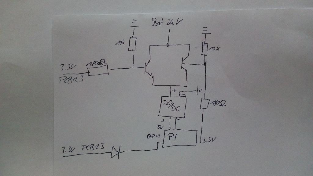
Beides würde den PI aus dem Leben reißen und mögilcherweise die SD Karte zerstören. Ich habe mir die bisherigen Anregungen angesehen, nun aber doch eine eigene Platine erstellt. Schaltplan siehe Anhang.

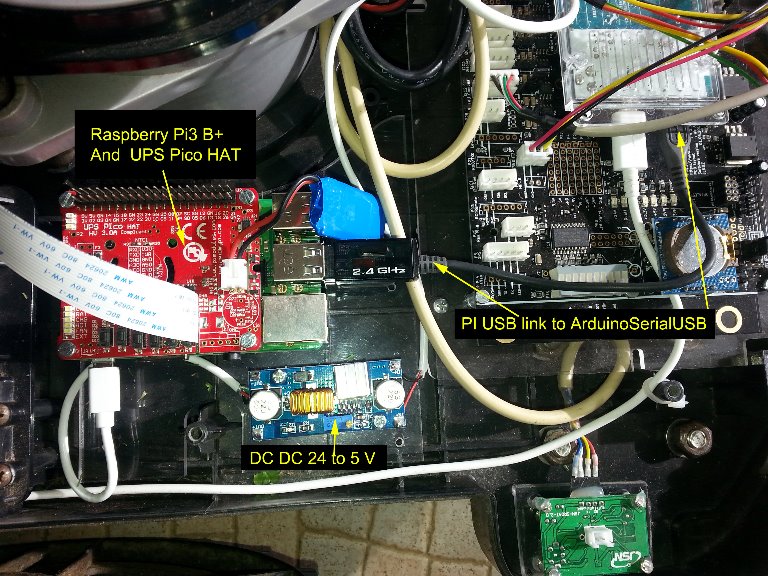
Das ganze läuft so ab. Sobald der Mower eingeschaltet wird, schaltet ein 3.3V Pin (vom DC/DC Pin Header) den ersten MOSFET (Irliz44n) durch. Somit wird der DC/DC Konverter mit Strom versorgt und liefert 5V für den PI. Dieser bootet nun. Ich habe einen OrangePI, dieser hat einen 3,3V Pin vom Spannungsregler am Pin Header. Solange der PI aktiv ist, liefert der Pin 3,3V. Ist der PI heruntergefahren, liegen keine 3,3V mehr vor, auch wenn der PI noch mit der Spannungsquelle verbunden ist.
Diese 3,3V nutze ich nun zum schalten eines zweiten MOSFET.

Zusätzlich gibt es eine Verbindung von den 3,3V des Mower zu einem GPIO Pin des PI (Sense).

Wird nu das PCB abgeschaltet (wegen Unterspannung, Schalter etc.), merkt dies der PI über die GPIOs und leitet einen Shutdown ein. Zeitgleich öffnet der erste MOSFET. Sobald der PI heruntergefahren ist, öffnet sich der zweite MOSFET durch das Wegfallen der 3,3V vom PI und die Schaltung ist stromlos.

Was meinen die Experten dazu? Reicht die Schaltung so aus? Irgendwelche Bedenken bezüglich der Bauteile, Ströme etc? Ich kenne mich da wirklich nicht aus.

The main issue I have is that my main switch is reachable outside the chassis.
It occured several times that the main switch gets switched to off either by an obstacle (tree) or by my children. Both cases may kill my SD card.

So I continued thinking about a solution and may found one. Please find schematics attached.

The PCB is direclty connected to battery, so powering off by main switch does not influence it.

As soon as PB 1.3 gets powered on, 3,3V coming from PCB switch a MOSFET (Irliz44n) to on. This powers the DC/DC converter which provides 5V for PI.
PI does now boots up. I use an OrangePI Zero which provides 3.3V over pin header if it is running (after shutdown 3,3v is lost). I use this 3.3V to enable a second MOSFET so PI is able to keep DC/DC alive.

If PCB1.3 is switched off (Undervoltage, Idle, Switch), PI recognise this by monitoring 3,3V from PCB1.3 via GPIO. Also MOSFET1 is open now. If GPIO is low, PI will shutdown. After shutdown is complete, 3,3V coming vom PI gets lost and opens MOSFET 2.

What do you think? Any issue with current flow or used parts? PLease let me know, I'm absolutely noob in electronics
Attachment: https://forum.ardumower.de/data/med...dumower-PI-switch_Sheet-1_20180509085223.png/
 
Zuletzt bearbeitet von einem Moderator:
Oben