Du verwendest einen veralteten Browser. Es ist möglich, dass diese oder andere Websites nicht korrekt angezeigt werden.
Du solltest ein Upgrade durchführen oder einen alternativen Browser verwenden.
Du solltest ein Upgrade durchführen oder einen alternativen Browser verwenden.
PCB 1.2 Erstinbetriebnahme
- Ersteller pemiso
- Erstellt am
Hi all.
I have a big problem with the Battery voltage mesurement by the arduino.
PCB v1.2 all DC DC converter instaled and corectly adjust.
Workarround about the capacitor OK.
In PFOD with the USB not connected the value is 30 Volt
In PFOD with the USB connected to arduino the value is correct 25.8V
I try to make the ADC calibration again , no change.
I test all the tension all seem to be OK.
I try to add a video and hope it's work.
Thanks
kurzschuss
Administrator
Can you ever please take some pictures of a board so that I can recognize where the components?
greetings Uwe
greetings Uwe
Hi.
Here the photo.
Attachment: https://forum.ardumower.de/data/media/kunena/attachments/3545/DSCN0275.jpg/
Here the photo.
Attachment: https://forum.ardumower.de/data/media/kunena/attachments/3545/DSCN0275.jpg/
Zuletzt bearbeitet von einem Moderator:
I think there is a second Strange thing.
I have exactly the same problem than MILOS in my testing of the charging battery.
The relay stay on after i disconnect the charger and the value in Pfod are not correct but i think the Battery is charging.
Here the config .
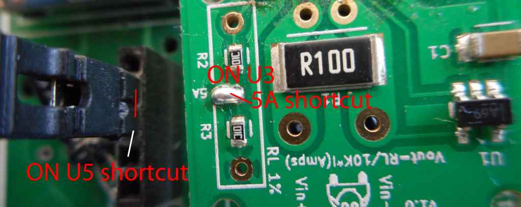
D3 D4 D7 SHORTCUT
U4 C1 C4 R17 RV1 REMOVED
U3 IN PLACE
R19 SHORTCUT
JP5 CLOSE
JP7 CLOSE
I really don't understand how the relay can stay ON whithout the charger and JP4 removed.
The only possibility is via StationLed ??? PinchargeVoltage ??? or U3 ???
I order 2 new INA169 and i think i try a new Arduino mega to be sure.
Hope it's solve the problem
Again thank you for all your very clear post and anwer
By.
I have exactly the same problem than MILOS in my testing of the charging battery.
The relay stay on after i disconnect the charger and the value in Pfod are not correct but i think the Battery is charging.
Here the config .
D3 D4 D7 SHORTCUT
U4 C1 C4 R17 RV1 REMOVED
U3 IN PLACE
R19 SHORTCUT
JP5 CLOSE
JP7 CLOSE
I really don't understand how the relay can stay ON whithout the charger and JP4 removed.
The only possibility is via StationLed ??? PinchargeVoltage ??? or U3 ???
I order 2 new INA169 and i think i try a new Arduino mega to be sure.
Hope it's solve the problem
Again thank you for all your very clear post and anwer
By.
kurzschuss
Administrator
I see 2 things that are not in order
On the INA169 the solder bridge for the 5A range is missing
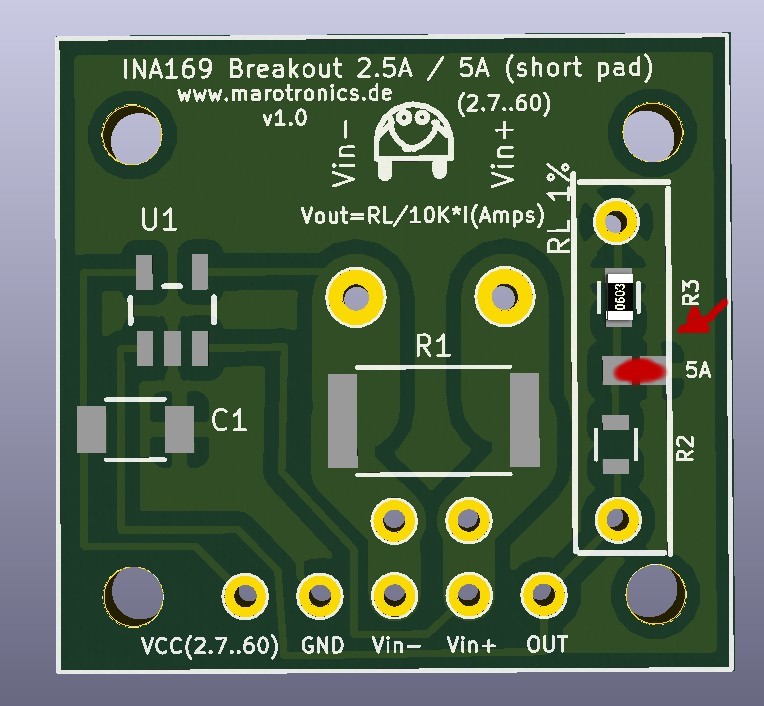
U5 I see unfortunately not really on the photo. But probably there is wrong, the solder bridge.
So U5 must look
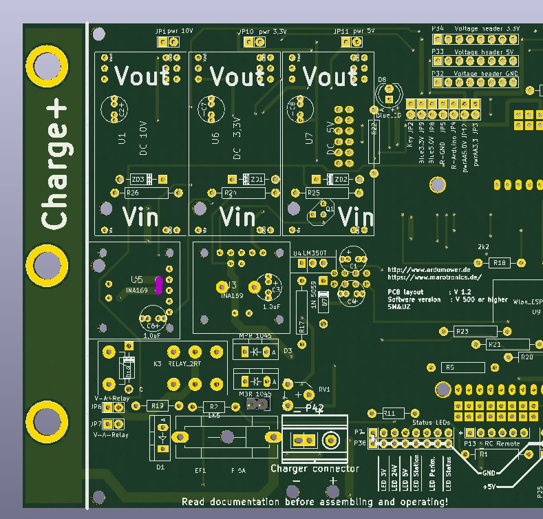
D3 D4 D7 SHORTCUT ->OK
U4 C1 C4 R17 RV1 REMOVED ->OK
U3 IN PLACE -> OK See photo for solder bridge
R19 SHORTCUT -> ok or Diode 1n4148
JP5 CLOSE ( JP5 permanent store in charging station without shutdown / JP4 Charge - Arduino on cargo in and out
JP7 CLOSE -> OK
JP1 must be closed. This is the power supply for the Arduino
JP3 or JP10 Power Supply 3.3V of sensors for the internal power of the Arduino or Step Down DC-DC Converter
JP11 or JP12 5V power supply of the sensors on the internal voltage of the Arduino or the Step Down DC-DC Converter
Gruß
Uwe
Attachment: https://forum.ardumower.de/data/media/kunena/attachments/1259/INAU5.jpg/
On the INA169 the solder bridge for the 5A range is missing
U5 I see unfortunately not really on the photo. But probably there is wrong, the solder bridge.
So U5 must look
D3 D4 D7 SHORTCUT ->OK
U4 C1 C4 R17 RV1 REMOVED ->OK
U3 IN PLACE -> OK See photo for solder bridge
R19 SHORTCUT -> ok or Diode 1n4148
JP5 CLOSE ( JP5 permanent store in charging station without shutdown / JP4 Charge - Arduino on cargo in and out
JP7 CLOSE -> OK
JP1 must be closed. This is the power supply for the Arduino
JP3 or JP10 Power Supply 3.3V of sensors for the internal power of the Arduino or Step Down DC-DC Converter
JP11 or JP12 5V power supply of the sensors on the internal voltage of the Arduino or the Step Down DC-DC Converter
Gruß
Uwe
Attachment: https://forum.ardumower.de/data/media/kunena/attachments/1259/INAU5.jpg/
Zuletzt bearbeitet von einem Moderator:
Hi
Thanks for your answer .
Now i understand what you want to see.
U3 and U5 i take a better picture.
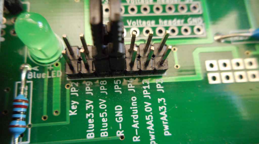
JP1 JP10 AND JP11 are closed

R19 Shortcut and JP7 Closed
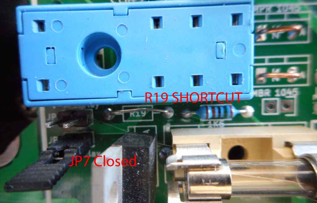
JP5 Closed I understand the difference between JP4 and JP5
The 2 problems are:
1 the value of Battery Voltage in Pfod Setting Battery is correct when Arduino is powered by the USB and wrong if i disconnect the USB.
2 When the mower touch the charging station the led station is on the relay is on but when i remove it from the station the led come OFF but the relay stay ON like in Milos post.
Maybe a diode instead of the R19 shortcut can solve this issue.I test and tell you.
This Week i receive a new Arduino and new INA169 so i try and hope it's that.
Is it normal i can't put a video (88 Megas) with the Add File option like for picture ?
Again thanks a lot.
Attachment: https://forum.ardumower.de/data/media/kunena/attachments/3545/1_2016-08-01.jpg/
Thanks for your answer .
Now i understand what you want to see.
U3 and U5 i take a better picture.
JP1 JP10 AND JP11 are closed
R19 Shortcut and JP7 Closed
JP5 Closed I understand the difference between JP4 and JP5
The 2 problems are:
1 the value of Battery Voltage in Pfod Setting Battery is correct when Arduino is powered by the USB and wrong if i disconnect the USB.
2 When the mower touch the charging station the led station is on the relay is on but when i remove it from the station the led come OFF but the relay stay ON like in Milos post.
Maybe a diode instead of the R19 shortcut can solve this issue.I test and tell you.
This Week i receive a new Arduino and new INA169 so i try and hope it's that.
Is it normal i can't put a video (88 Megas) with the Add File option like for picture ?
Again thanks a lot.
Attachment: https://forum.ardumower.de/data/media/kunena/attachments/3545/1_2016-08-01.jpg/
Zuletzt bearbeitet von einem Moderator:
HI.
Good day 2 problems solved.
I have received my new original arduino mega and the battery voltage is now correct with or without the USB connected.
For the problem about the charging relay staying on after disconnect the charging station.
I simply change the way for control charging and use the JP4 instead of JP5.
Now the Arduino can switch off the relay via Q1 and it's work perfectly after setting the correct:
charging start if voltage is below in PFOD .
Thanks a lot
By
Hi again.
PCB1.2 Standard config with 2 MC33926,Denna motor 24V 1.6A
Azurit 1.05
I search in all the forum but never i find this.
In PFOD the motor current and power of left motor are nan ??????
What is nan ?
There is no error and the motor work.
I already view this ,it's disapeare and come back again (Bad solder or Problem in Motor driver ??)

If you can help.
Thanks.
Attachment: https://forum.ardumower.de/data/media/kunena/attachments/3545/10.jpg/
PCB1.2 Standard config with 2 MC33926,Denna motor 24V 1.6A
Azurit 1.05
I search in all the forum but never i find this.
In PFOD the motor current and power of left motor are nan ??????
What is nan ?
There is no error and the motor work.
I already view this ,it's disapeare and come back again (Bad solder or Problem in Motor driver ??)
If you can help.
Thanks.
Attachment: https://forum.ardumower.de/data/media/kunena/attachments/3545/10.jpg/
Zuletzt bearbeitet von einem Moderator:
Hi Boilevin
congratulations for your success!
Regarding your error message: nan stands for "not a number". https://en.wikipedia.org/wiki/NaN
congratulations for your success!
Regarding your error message: nan stands for "not a number". https://en.wikipedia.org/wiki/NaN
Hi Peter.
Again thanks for your answer.
Finaly it's works .
.
I think the problem was in motorSenseLeftScale the value read in Pfod was 'inf' so the sense and power was 'ana' but WHY ???
After load the same code again Azurit 1.05 factory setting and then i have the good value in sense and power.
So now i need to make the perimeter tracking work better because it's not smooth at all. :woohoo:
But i don't find a video with a smooth tracking with Ardumower soft and as i used DENNA motor the PID for motor and tracking are not correct at all.
If you have one ?
Hope for your new mower all is OK.
Have a good week.
BY.
Again thanks for your answer.
Finaly it's works
.I think the problem was in motorSenseLeftScale the value read in Pfod was 'inf' so the sense and power was 'ana' but WHY ???
After load the same code again Azurit 1.05 factory setting and then i have the good value in sense and power.
So now i need to make the perimeter tracking work better because it's not smooth at all. :woohoo:
But i don't find a video with a smooth tracking with Ardumower soft and as i used DENNA motor the PID for motor and tracking are not correct at all.
If you have one ?
Hope for your new mower all is OK.
Have a good week.
BY.
Good morning Boilevin,
very good - you made it
By the way - you know of the latest version azurit 1.0a6 ?
Ok perimeter tracking is not smooth with DENNA and original ardumower pid parameters.
I think I saw a video of Alexanders ardumower following the perimeter pretty smooth.
Hoping to have some time within the next few days to complete my brandnew ardumower and also my DENNA with senderboard built in the original DENNA-station. Then I try to optimize perimeter tracking smoothly ...
Have a nice day.
Peter
Endlich hatte ich wieder Zeit und habe das neue 1.2 Mainboard mit Fahr- und Mähmotoren am Rechner nur mit serieller Konsole in Betrieb genommen. BT Verbindung ist eingerichtet und läuft. Dann zusätzlich ArdumowerAkku eingeschaltet. OHNE Odometrie: linker Radantrieb ok, rechts läuft sofort Vollgas rückwärts und Mähantrieb brummt auch gleich los.
Also Eins nach dem Anderen:
Vielleicht wird das mit ODO besser? Zum anschliessen fehlen, soweit ich bisher verstanden habe, noch Pullup-Widerstände? Frage: heißt das, alle 4 Signaleingangspins an P8 und P9 mit 4k7 an Plus?
Alles ist Original Ardumower mit Azurit 1.0a6.
Danke für Euren Rat.
Gruss ... Peter
kurzschuss
Administrator
Was und wie ist hier beschrieben https://github.com/Ardumower/ardumo...hield svn 1.2 und V0.5/WorkaRound20150527.pdf
Gruß
Uwe
Gruß
Uwe
kurzschuss
Administrator
Dir auchSo - inzwischen konnte ich die Anfangsprobleme beseitigen. Irgendwann nach mehreren Tagen Frust kam ich auf die glorreiche Idee, den Mega mal auszutauschen. Siehe da, es klappt ...
Jetzt geht es auf den Rasen zum Perimetertest ... toi toi toi.
By the way eine Frage zu einer Ungereimtheit bei stationären Testen (Mäher im Arbeitszimmer aufgebockt:
Im 2D-Plot der Odometrie gefiel mir bei Vorwärtsfahrt die saubere Gerade, auf der ich dann bei Rückwärtsfahrt eigentlich in umgekehrter Richtung zurückzufahren gedachte.
Bei Rückwärtsfahrt treten jedoch leichte Kurvenfahrt und plötzliche Korrekturen als Knicke im Verlauf des Plots auf.
Ist die Rückwärtsfahrt nicht odometrie-geregelt?
Bei Vorwärtsfahrt wird ja über die Encodersignale der zurückgelegte Weg beider Räder (Schlupf mal außer Acht gelassen) geregelt.
D.h. die Motoren werden entsprechend variabel angesteuert.
Bei Rückwärtsfahrt scheint das nicht der Fall zu sein - oder???