MEGA vs DUE on PCB

Dear All, I have two question to complete my PCB 0.5

1) Do I understand corretly? If I use ARDUINO DUE ----> Lp0-Lp15 must be open, as they are on PCB.
If I use ARDUINO MEGA ----> Lp0-Lp15 must be welded (short-circuit)

SI-NO.jpg


lp0-15.jpg


2) If I use ARDUINO DUE---> DC/DC 10V (must be used), DC/DC 3V (must be used)....DC/DC 5V (don't needed)
If I use ARDUINO MEGA---> DC/DC 10V (must be used), DC/DC 5V (must be used)....DC/DC 3V (must be used)

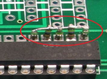
3) If I use arduino MEGA is it necessary pull-up odometry ad workaround (see attached)?? After modification I need to weld Lp0-Lp15??

modifica1.jpg


thank you all
 
I can use also MEGA, but I would like to understand If I have to weld Lp0-15 or not, and what about pull up of odometry.

Thank you
 
Hello

I'm also trying to use the ARDUINO DUE on a PCB 1.2, but I'm a beginer in electronic, so I will really appreciate some confirmation. Thanks in advance :)

1) From close observation of the PCB and measurements, all lotpads are closed by a tiny bridge on the back of the PCB 1.2, except the lp3, hence the "Fehler Korrectur" for MowRightSence (pin18). This correction should only apply for Mega.

From my understanding, all lotpad (lp0 > lp7, lp8 > lp15, [strike]lp16 (named lp17 on pcb), lp17 > lp20 (named lp21 on pcb)[/strike], lp21 (named lp20 on pcb) lp22, lp23 and lp24 > lp31 must be opened to use the DUE, in order to avoid 5 V to arrives on a DUE pin.

Edit : lp16 > lp20 do not need modification to use the DUE (10V supply, gnd, 5V, 3.3V, reset), idem for lp24 > lp26 (not used), lp27 (ground).

Then a 2 pins connector have to be welded on each lotpad. On these pins we either plug a jumper (3,3 V input) or a voltage dividor made with 2 resistors of 10 and 20 kOhm for 5 V input (for example: ultrasonic inputs arriving on lp21, lp22 and lp23).

Edit : The U10 module seems to have also something to do with 5/3,3 V conversion but no idea about it ! Please help.

2) The use of either the internal 5 V supply through jumper JP12 or an external 5V DC/DC and jumper JP11 will depends on how much power is needed by the 5 Volt only sensors and modules plugged to the board.

3) I guess (not sure at all) when using the DUE, the resistors of the voltage divider for odometrie inputs (needed because MC33926 works with 5 V supply) will also assume the function of the pull up, so extra resistors are not needed.

PS: I've seen the drawing of an adapter board for the DUE somewhere in the german forum, but it seems that no corresponding PCB is available in the shop.

Edit2 :I have found the DUE adaptor board, was not in forum but in download and the Kicad software is necessary to open it. I just made a picture (attached), so it is easier to see it. And it answer questions about lotpad ;)

Thank you for taking time to answer ;)

Jacques
Attachment: https://forum.ardumower.de/data/media/kunena/attachments/2809/DuePcbV0.5.png/
 
Zuletzt bearbeitet von einem Moderator:
Hello

More on DUE ... , some feedback
The odometry is not working when using voltage divider. But without, YES it does. What I understand : the input for odo have pullup activited in the software, so the voltage is normally high (3.3 V with DUE) and the tick drive the input LOW. So inputs with pullup do not need voltage divider. It is exactly the same for the hal sensors (the very small ones from the shop) I adapted to the mowers motors to measure rotation speed.

There is also no need for voltage adapter for the I2C modules DS1307C (real time clock) and GY80 (IMU), both have on board pullup resistors and work with 3.3 V. BUT the RTC supply line (VCC) on the pcb must be cut from the 5V and connected to the 3,3V supply line. It would an improvement on a new pcb version to have the RTC supply voltage selectable through a jumper, as it is already done for the bluetooth module.

edit : The buzzer cannot work as foreseen, because DUE output can only source 3 or 9 mA depending of the pin. A buzzer needs between 20 and 50 mA, according to type. The solution is to drive it through a transistor (for instance a BC547 from the shop):
pin 53 -> 1.5 kOhm -> transistor Base
- buzzer -> transistor Collector
ground -> transistor Emittor
+5 V -> + buzzer

The software does't not compile (1.0a4 azurith, IDE 1.6.6) because the NOBLOCK option for interrupt is not available for DUE. Once commented, it is OK. It might not be a problem because the DUE is quick enough. According to comments, problems arise with Mega when acquisition frequency for perimeter sensor is set at 38 kHz, but it also works at lower frequencies (9615 Hz or 19230 Hz or 28845 Hz).

Jacques
 
Oben