How to connect the protector board with the pololu

jonathanbyrn

New member
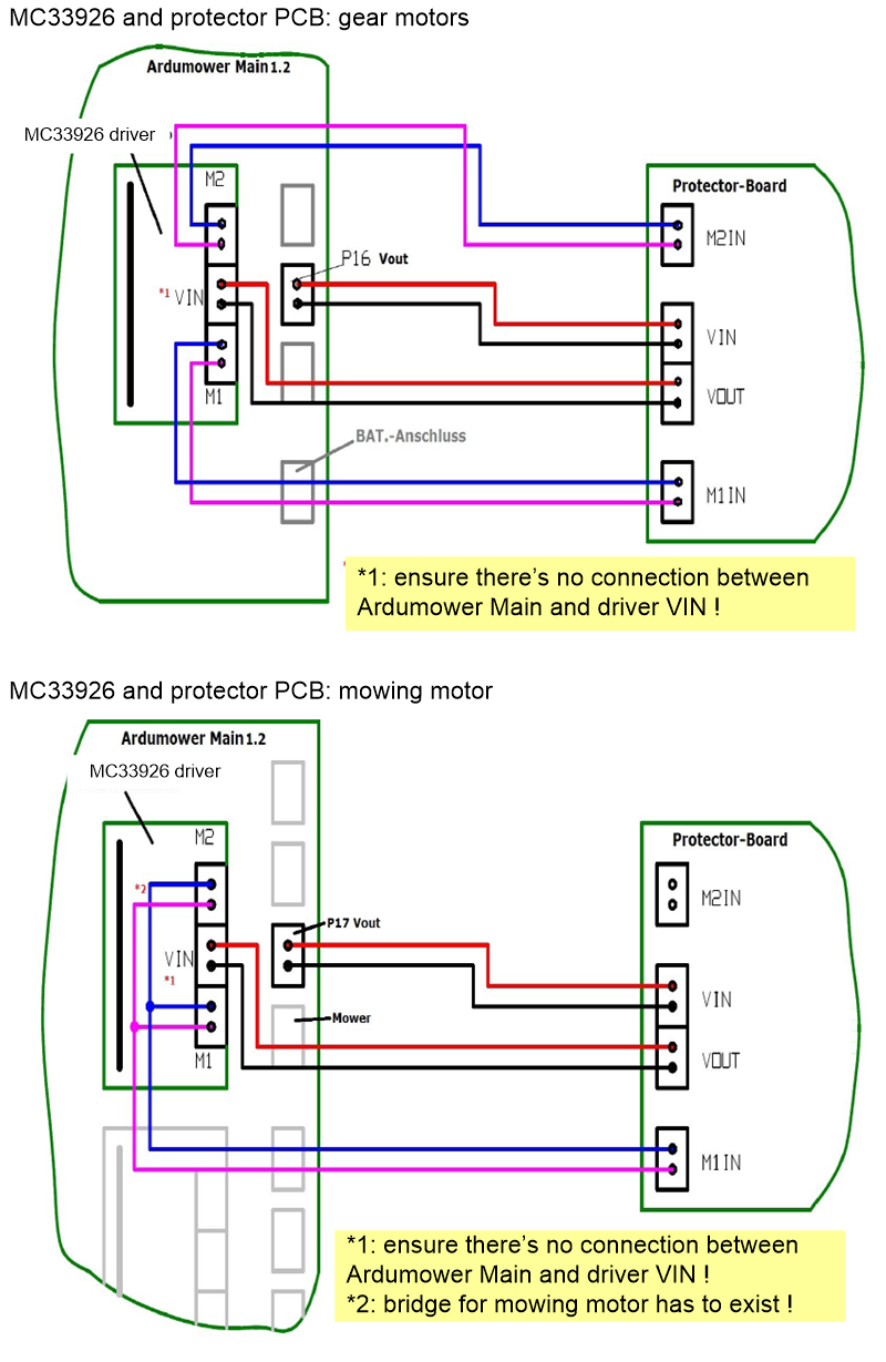
I am connecting my pololu board to my driver protection boards using the protector board workshop documentation. Unfortunately it is not clear what to do in google translate. My PCB is connected to the VIN and GND pins on the pololu board but the diagram shows the VIN connected to the protector board VOUT and the P16 connected connected the protector board VIN.

The pins connect the VIN to P16 so they will have to be removed. Does anyone have any pictures of how they connected the protector board out to the VIN and how they anchored the board to the PCB?
 
Before using the protectorboard, you connected VIN of to motordirver to 24V of the mainboard. P16 is also conected to 24V of the mainboard. Under this circumstances you have to remove VIN of the motordriver from the 24V of the mainboard because VIN gets now 24V from the protectorboard.

P16 supplys 24V from the mainboard to the protectorboard. And the protectorboard supplys 24V to VIN to the motordriver MC339260.

Thats how I unsderstand this.
 
Protector_wiring.png
 
Hello Jonathan,

Am I right, that you removed one pin from the second row (2 pins, 3 pins, 2 pins)?
As far as I understand the text in the workshop paper, I have to remove the GND and the VIN pin from the first row (the long one) and then to connect the mainboard and the protector board as shown in the document. Is that right? I marked the pins I want to remove in the attached file.
Attachment: https://forum.ardumower.de/data/media/kunena/attachments/3922/20170320_213655.jpg/
 
Zuletzt bearbeitet von einem Moderator:
no, leave the back row with 2-3-2 pins. I only removed the VIN and GROUND pins at the front. The pin is hidden by the post-it and I didn't notice!
 
https://github.com/Ardumower/ardumower/blob/master/Dokumentation/Protector%20Board/WORKSHOP%20Protector-Board.pdf

Auf den Bild bleibt auf der rechten Seite alles wie es ist. Der Rote Pfleil der auf den Vin und GND PIN zeigt.
Dort braucht nichts geändert zu werden.
Die Änderungen müssen auf der linken seite erfolgen. Dort die 6 Stiftleisten entfernen(m2out2,m2out1,Vin,GND,m1out2,m1out1) und dafür 3mal die 2poligen Schraubklemmen einlöten

In the picture everything on the right side remains as it is. The Red Pfleil shows on the Vin and GND PIN.
There nothing needs to be changed.
The changes must be made on the left side. Remove the 6 pin strips (m2out2, m2out1, Vin, GND, m1out2, m1out1) and solder in 3x2-pin screw terminals

Gruß
Uwe
 
Hi,

I attached to pictures of my driver to be clear and sure.

The describtion of Jürgen (author of the workshop) makes me a little bit uncertained: "it is very important, that the VIN of the driver has no connection to the 24V of the main board" . The driver has two connections labeled with VIN, the VIN pin is connected with the mainboard for sure. Therefore I thought, that I have to remove the pins, because the 3 screw terminals were in the package of Marotronics already.

Please confirm, that my board is already assembled in the right way for the use of the protection board.

---

Ich habe zwei Bilder vom Motortreiber angehangen, um sicherzugehen.

Die Beschreibung von Jürgen als Workshop-Schreiber verunsichert mich ein wenig: "Es ist ganz wichtig, dass der VIN vom Motortreiber keine Verbindung zu den 24V der Ardumower-Main hat (...)". Am Treiber sind zwei Kontakte mit VIN beschriftet und der an der Stiftleiste ist auf jeden Fall mit der Hauptplatine verbunden. Darum dachte ich, dass ich diesen Pin entfernen muss, denn die 3 Schraubklemmen waren auch schon von Marotronics standardmäßig mitgeliefert.

Bitte seid so lieb und bestätigt kurz, dass das Treiberboard bereits richtig bestückt ist für die Nutzung des Protection Boards.
Attachment: https://forum.ardumower.de/data/media/kunena/attachments/3922/20170321_065909.jpg/
 
Zuletzt bearbeitet von einem Moderator:
Thanks a lot for the dead pin information. More and more I understand the plans!

Full of joy to see my mower moving through my living room today, I started to inspect the connections from the board and the driver. The screw terminals of the driver are very small. My 1.5mm² cables do not fit... Which cable diameter would you recommend?

--

Danke für die Info mit dem toten Pin. Mehr und mehr verstehe ich die Pläne...

Voller Vorfreude heute meinen Mower fahren zu sehen habe ich die Anschlüsse untersucht. Allerdings sind die Schraubklemmen vom Treiber sehr klein, meine 1,5mm² Kabel passen da nicht.... Welchen Querschnitt würdet ihr empfehlen?

Edit: If I try to squeeze the cable ends multiple times, the 1.5 could fit... - Wenn ich die 1,5er Aderendhülsen einfach mehrfach quetsche, dann könnten sie passen...
Attachment: https://forum.ardumower.de/data/media/kunena/attachments/3922/20170321_185510.jpg/
 
Zuletzt bearbeitet von einem Moderator:
Oben