Help translating PCB version 1.2 instructions.

megacue

Member
Good morning.

Since I cannot read German, I am helping myself with Google translator, but there are occasions when this is barely useful.
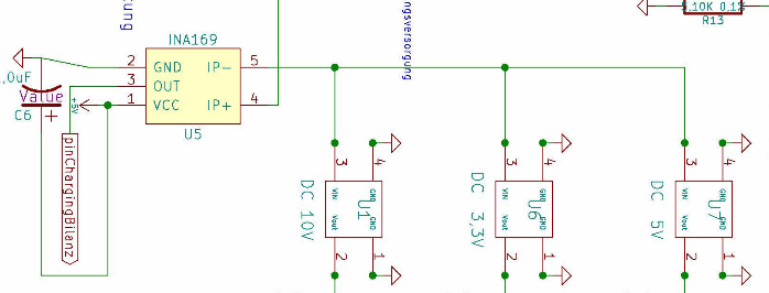
For instance, I have trouble understanding what is written about the deprecated INA module (U5), namely: what does

"Wenn dieser nicht bestückt wird sind der Vin Eingang und Vout Ausgang zu Brücken damit die Stepdownwandler mit Spannung versorgt werden. Dies kann an der Seite gemacht werden wo die 2 Stiftleisten vorhanden sind. Im Plan Kontakt 4 und 5"

mean? Please some kind soul help me and all present and future Spanish users, thanks a lot.
 
Good morning Manuel,

... If it is not implemented, you have to connect Vin and Vout to get power on your stepdown voltage regulators. For this choose Pin 4 and 5 as shown in the schematics ...

Hope this helps you a little bit. Have a nice day. Peter
 
Hello Peter, thanks for replying, it helps indeed.

So if I am not wrong I would have to connect together pins 4 and 5, the same pins 4 and 5 where Vin+ and Vin- from the INA module would otherwise connect, right? That's all the sense I can make from the description, but for this to work Vin/Vout must be the wrong designations and Vin+/Vin- the right ones.


Am I utterly wrong, as well as confused?
 
Hi Manuel,

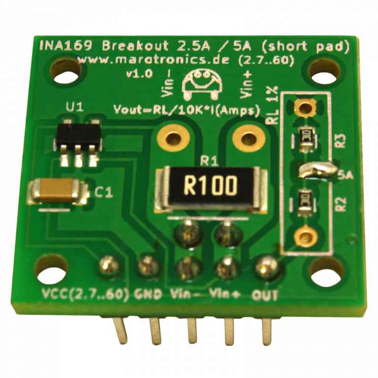
The reason for this is to bypass the not implemented ina module. For my understanding we have to connect Vin+ and Vout so that voltage is connected to stepdown regulator.

Do not connect Vin- to Vin+ because this would be a shortcut!
 
I can definitely figure out where Vin+ (IP+) is but, where is Vout? Besides, pins 4 and 5 in the schematics do seem to connect to IP+/IP- (Vin+/Vin-).

INA169-Analog-DC-Current-Sensor-Breakout-60V-25A-5A-Marotronics_b5.jpg


INA_U5.png


I am sorry for being so obtuse, I have the feeling that I am missing something obvious.

Thanks again for your help and your patience.
Attachment: https://forum.ardumower.de/data/med...ensor-Breakout-60V-25A-5A-Marotronics_b5.jpg/
 
Zuletzt bearbeitet von einem Moderator:
Ok Manuel,

It seems my last statement has been wrong:
I would connect pins 4 and 5 - means to connect Vin- (that is the input to be monitored) and Vin+ (that is the input leaving the ina module). So the ina module is bridged.
 
New question: could somebody please care to explain what the problem with the Kondensator Netzwerk is? As written in the instructions:

"Bei der Auslieferung des Paketes ist uns aufgefallen das das Kondenstornetzwerk 1 Pin zuviel hat.
Der äußere Pin sollte umgebogen werden und beide Netzwerke sind etwas schräg zueinander
einzubauen. Dann reicht der Platz aus. Die Seite mit dem Punkt muss jeweils nach außen."

I have the feeling some word was left out of the explanation. Pin 1 has too much ... "something"? A picture would be worth a thousand words.
 
Hello Manuel,

the Text says, that the Condensator net (dont know if its the correct translation) has 1 Pin too much. The outer Pin has to be bend, because there is no hole in the PCB. You also have to put it in an angle so both Condensator nets have enough space. The dot on the Condensator net has to be placed outside.
Its a little tricky to describe but you can see some pictures here: http://www.ardumower.de/media/kunena/attachments/1259/ArdumuverBestckung2015-04-221115.pdf
Regards
Wolfgang
 
Yet another question: what is a "Stabelleisten"? As in:

"Folgende Fehler oder Verbesserungen sind zur Zeit bekannt:
-Die ISP Leiste von den Mega muss ausgelötet werden wenn der Mega auf Stabelleisten gesetzt
werden sollte und die Uhr darunter ist. Eine alternative ist die Uhr wenn vorhanden auf die Rückseite
zu setzen. Ich habe bei mir Stabelleisten eingesetzt und unter den Arduino die Uhr gesetzt. Hat den
Vorteil das der Mega höher sitzt und man die Möglichkeit hat den USB Stecker einzustecken ohne
die Platine zu entfernen.
Ich bin hergekommen und habe bei den Anschluss der Ladespannung und des Akkus ein weiteres
Loch gebohrt. Die Platine gegen das Licht halten dann sieht man wo keine Leiterbahnen sind. Dann
bin ich hergekommen und habe sie auf der Rückseite mit den Pin verbunden."

Thanks in advance.
 
Hello Manuel,

Stapelleisten is a stackable pin header - also used on shields.
These can be used, when you want to raise the position of the Mega fx. to put the RTC under the Mega or to get a higher position for the USB. You can also put the RTC on the backside of the PCB or find other solutions to increase the distance between Mega and PCB.
In case you want to install the RTC under the Mega, you also have to desolder the ISP pins from the Mega to make space for the RTC.

Regards
Wolfgang
 
New question for you, kind gentlemen.

Talking about Diode D2, what does "Bestücken unklar wegen evl Drehrichtungsumkehr" mean exactly? Google translator is making a mess out of it, as it fancies to do.

Oh and what would "evl" mean? I see it written a lot around and has me pretty confused.

Thanks in advance.

Manuel
 
Hallo Manuel,

"Bestücken unklar wegen evl Drehrichtungsumkehr" means that mower blade run in the other direction. My english is terrible.
evtl means in german "eventuell" (possible)

Marco
 
Almost there ...

Would somebody please reword for me the procedure for compass calibration? Google translator no good :huh:

"Jede der 6 Seiten des Moduls einmal Richtung
Norden halten und das Modul solange kippen
bis sich das Minimum und Maximum der
Achsen nicht mehr ändert (kein Ton mehr
ausgegeben wird):"

Thanks in advance.
 
"Hold each of the 6 module sides to North direction and tilt the module until minimum and maximum of the axis does not change anymore (until no tone is outputted anymore):"


Found at:
http://wiki.ardumower.de/index.php?title=IMU#Compass_sensor
 
AlexanderG schrieb:
"Hold each of the 6 module sides to North direction and tilt the module until minimum and maximum of the axis does not change anymore (until no tone is outputted anymore):"


Found at: http://wiki.ardumower.de/index.php?title=IMU#Compass_sensor[/quote]
Thanks Alexander. I must remember to check the wiki when I have doubts.

Please excuse if I ask stupid questions, I am learning as I try to understand the concepts; when you (the Ardumower wiki) say "tilt the module", does this mean "turn the module around the north-south axis"?

Gruss

Manuel García
 
Zuletzt bearbeitet von einem Moderator:
Oben